I have a simple problem I would like to automatise as it shall be applied to a lot of plates.
My model geometry is constructed in RHINO via GH. These RHINO surfaces are converted into TEKLA plates - they are very recurrent planar plates of about rectangular shape with 4 or 6 corners. I would simply like to make arc or line chamfers to some corners/handles. Is there a possibility within the GH-TEKLA link or has anybody developed a script to do the task? I have a lot of plates being generated via GH-TEKLA link and having to deal with chamfers manually within TEKLA would be a huge drawback..
If fact what I need to do is EXACTLY what is documented in this video and in the figure below..
I guess it is a classical issue that many have gone through as to my knowledge chamfer option is not present in GH-TEKLA link.
indeed thank you very much for your quick reply. This seems very much what I look for.
I’ll test it early next week when I’ll get TEKLA finally installed. It will be version 2022 hence I’ll also do the file change the assembly reference you mentioned.
Would that be possible to provide the line chamfer type as well? I guess it’s a minor change in the script but I’m not expert in programming.
Thank you a lot for you support. Highly appreciated.
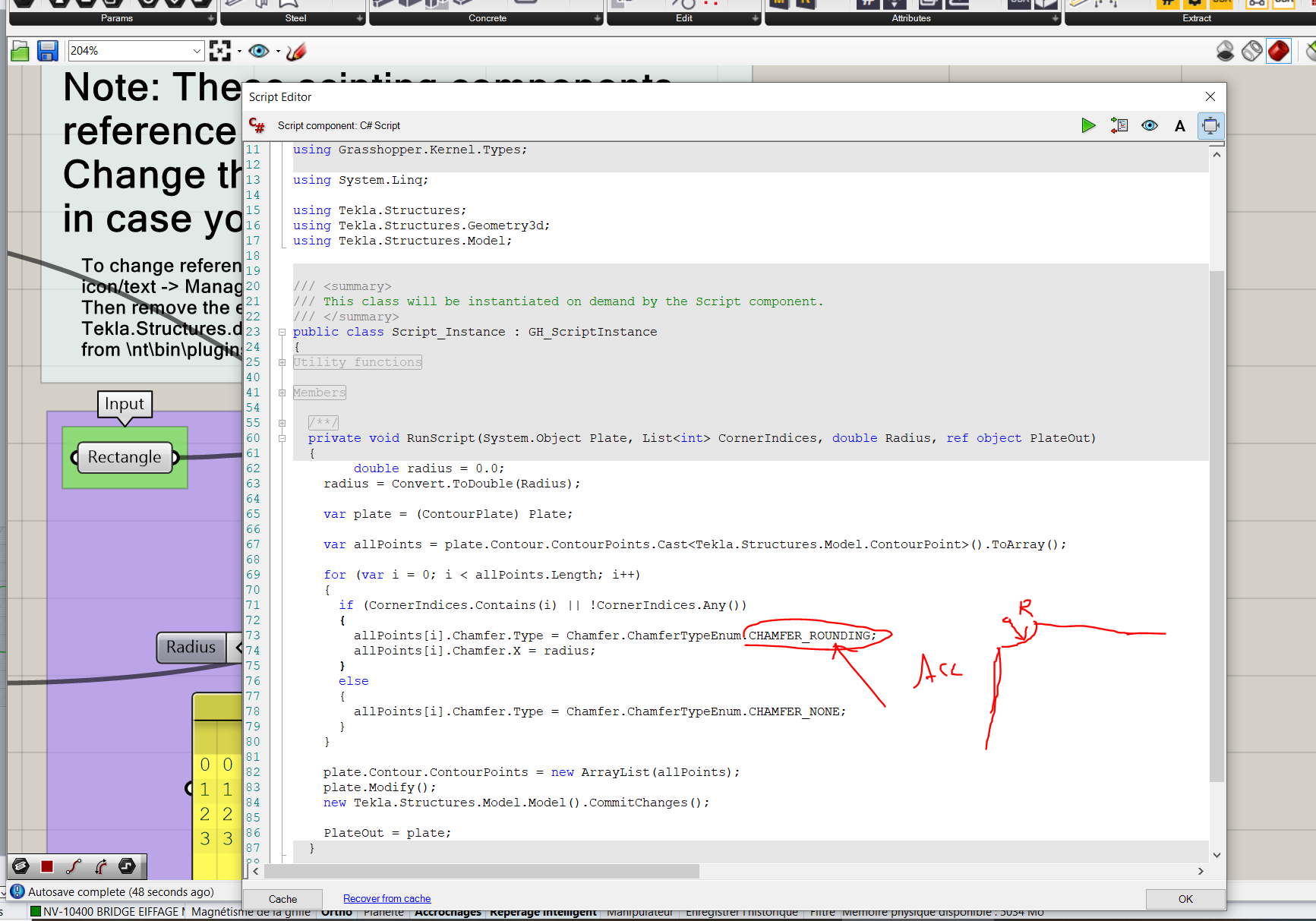
FYI, if you look inside the script, auto-completion will provide you the different Chamfer types in Tekla.
(Some values need two dimensions and will require an additional allPoints[i].Chamfer.Y)
I have a similar problem that I believe can solved with a similar C# component. I would like to control the offset values Dz1 and Dz2 for nodes of a plate in Tekla with my script in Grasshopper. Would anyone be able to help me making a C# component that is able to do so?
to begin with a huge THANK YOU to @magicteddy and @sajesh_pj for your support and the scripts. This is absolutely brilliant.
What I would like to achieve next and that I did not make it clear when I created the post is the possibility to chose different chamfer types depending on the handle / vertex of the plate. I have in fact one plate with 7 vertex, three of which have chamfers of different types.
Basically I would need a chamfer type option as entry data in the script in such a way to link each corner to a chamfer type.
Would that be possible guys? Any reply highly appreciated.
For both your requests, I think the solution is to separate the job between several components : creating Chamfers (with type and all options), then modifying the plate, then commiting changes to the model (which I separated in order to avoid several commits to Tekla, in case you want to use these components with tree structures).
I’m working completely blind because I don’t have Tekla Structures on my computer, however I used to work a lot with the Tekla API so I hope my solution will work !
@magicteddy which index problem have you found ? I just finished and I managed to make your previous script to work ! I understand that 0 is the first handle of the part.
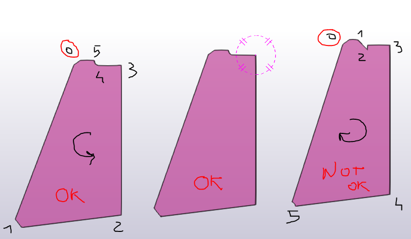
However I find now another problem. I tried to make it work for a list of about 200 parts I notice that despite the origin is always located at the same handle the numbering of nearby plates may follow either the clockwise or counterclockwise direction (see screen capture). Which is weird as despite the pieces are very similar (though not identical) they are generated in exactly the same manner within GR. Is there anything I can do to act on the handles numbering orientation?
Something like sorting the handles via the “sort along curve” component sot that I have them all in the counterclockwise direction? I truly hope on an affermative answer…
There was a mistake that didn’t associate the good chamfer to the correct contour Point. You may not have experienced it if you defined the complete list of values (0,1,2… N) as an input.
However I was definitely in the need of sleep as there was still a problem in the case you provided a single chamfer and several index. Should be corrected in this version. The only component changed is the ModifyPlate.
As for the orientation issue, I experienced that in the past… And there was nothing I could do about it
The thing that has to be checked first is the order of your input points before and after the LiveLink Plate component.
Deactivate any chamfer modification
Insert your 200 polylines in Tekla
Use Deconstruct Plate to get back the curve, explode it and check again for order.
To be extra sure, use the GetTeklaContourPoints C# component I added there.
If the order is not correct, then this comes from Tekla that just switches the order for no reason.
What could be done is to compute the index of the contour point using Closest Point, which at least would insert them in the right position. Still the ordering may lead to some issues when numbering and extracting drawings.
@magicteddy About the chamfer tool : Indeed I associated the whole list as I noticed that it did not work otherwise. I tested it and your latest script fixes those bugs. Excellent job. Thank you indeed.
About the orientation order : … in RHINO I get the same for all polylines hence I confirm that it is TEKLA massing up the order by changing it for no reason but I still confirm that the first point is always the same for all plates.
If I understand you well I changed you rectangle input component to my 200 RHINO polylines and the group you named “Plate with Chamfer” is rather without chamfer I suppose. By the way the point list component does not work or nothing is shown when associated to GetTeklaContourPoints or TeklaContourPoints C# components (perhaps a view setting to switch in TEKLA - if so sorry I’m very new to TEKLA). I also tried to follow your third bullet point ( Deconstruct Plate + explode) but I’m not sur I understood correctly. However even doing so no change on the result (attached is the file).
As it looks like there is no way to solve this VERY annoying issue can you provide with some detailed insight on the last resort you mentioned? How to compute the indexes of the contour by using Closest Point?
I see you modeled your plates vertically - I should have asked for this right way because it’s exactly the same case I encountered.
Is is possible for your project to insert them in XY plane ? It is very likely this solves your orientation issue.
Your file is also in meters and objects very far from the origin, I’m assuming then you are not using a reference point in Tekla. Maybe this is another way to explore.
I added comments, correction to the GetTeklaContourPoints and the workaround with ClosestPoint in the gh file.
Yes definitely, elements are completely vertical and I cannot really change the plane I’m afraid - then I did not even tried.
Yes RHINO is in meter and TEKLA in mm but indeed I have a base point defined to bring the first item about 20m to TEKLA origin to avoid modelling distortions and errors.
Unfortunately the workaround does not work : plate indexes keep the same numbering / orientation before and after Explosion+Closest point.
I added replies and comments to the GH file. By the way Point list related to TeklaContourPoint remains red. Any fixing to be done on that script too?
Unfortunately I think I will be obliged to do it manually by calling the indexes of the polylinine list which are aligned in one order (see at the bottom part in the file - fortuantely it seems like there are only two ordering schemes so that the task may not be impossible… ). In such case I would like to reduce manual work and call out one one ordering list in such a way that the complementary index list are called out automatically (with I guess the dispatch component). I just wonder how to deal with this basic list component and particularly the boolean pattern (see file).
If the indexes are not identical, this means that the polyline retrieved from Tekla using Deconstruct Plate has the Tekla orientation, whereas the indexes from the Explode component have the original indexes, that you know about.
This is not meant to fix the orientation in Tekla, but only to get it back in Grasshopper so the match can be made.
You do need to feed the CP index as new indexes, this should work !
But maybe you need to graft your polylines for this to work.
And maybe you need a Scale component (and perhaps Move) so the polylines are on the same location.
Yes indeed - thank you again.
Just a small tip in case modify plate component may not seem computing (no chamfers appearing at some corners) - you shall recompute everything pressing F5 or force a change (such as the chamfer type for instance) to any corner which are (apparently) not affected in TEKLA. That is likely to make them compute and show up in TEKLA too.
Try setting the Orient input of the Plate component to ‘false’.
Tekla changes the order of the input points to keep the up-direction of the plate in the global z-direction. This ensures that e.g. the Position depth offset behaves intuitively. Indeed the same happens if you insert a plate manually by picking points in either clock- or anti-clockwise direction.
If your plates are vertical, the up-direction is arbitrary, and in practice it will depend on small rounding errors of the vertex coords. The Orient option avoids the automatic flipping of the point order.