Dear users,
I have the following problem. I am creating pipes that run in floors as part of my master’s thesis. For this purpose I have modeled cuboids as floors. In this cuboid, in turn, pipes run. On the one hand I have created pipes around lines and on the other hand I have extruded them as circular surfaces. Unfortunately, when exporting to an FEM program (Ansys Fluent), I have the problem that the edges of the pipes are not round but angular. After multiple troubleshooting, the problem lies with Rhino. The circle is generally only generated as a polyline, at least when extruded, and thus the result is not a circular tube but an angular one. How can I manage to create an actually circular tube?
Thanks in advance


Exportmodell.3dm (308.5 KB)
exportmodell.gh (47.8 KB)
Hello- what file format are you exporting?
Please see also
https://www.hydraulicdesign.net/meshes.htm
https://wiki.mcneel.com/rhino/meshfaq
for an explanation of display meshes in Rhino and how that works.
-Pascal
It’s also possible that your export settings are incorrect - that the object is actually good and circular, but the export has been tessellated (polygonized). If you are exporting via GH, check how whatever component/plug-in you are using to export is doing the export.
Hey Pascal,
Hey Helvetosaur
i tried some like, 3dm itself, iges, dxf, dwg, stp, stl all with export schemes that should only display the curve.


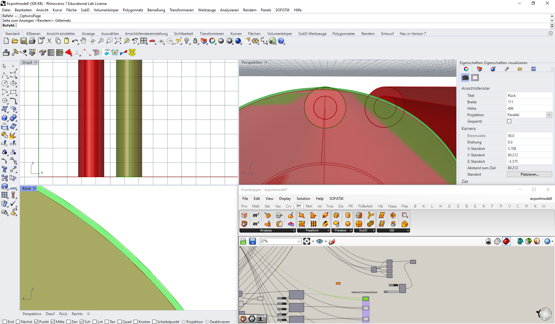
But as seen in the picture, the pipe ist not round the green silhouette differs from the black contour lines of the circle. This effect happens when extruded either as a pipe or as a circle. The extrusion must be ideal round though.
Hi @joshiachi,
Could you clarify: does your green and red illustration come from Rhino or Fluent?
Thanks
Jeremy
That is only the Rhino display mesh settings and actually has nothing to do with what is actually exported. The only way to know for sure is to post a file exported from your model here to check (with the export scheme used to export). I exported via DXF one piece of your model above (the box with two holes) using 2007 Natural and then re-imported it into Rhino - it came in as a closed polysurface that has round, cylindrical surfaces in the holes - as expected.
That being said, I’m not sure if it is in fact the software you are using for FEM’s import function that is tessellating (meshing) the surface objects on import, ISTR that FEM software works on meshes, not NURBS surfaces… but I might be mistaken on that.
Correct. From Ansys:
CAD Import and Meshing
From CAD import to geometry meshing, our flexible tools allow you to
automatically create meshes or hand-craft them. Ansys meshing can extract
fluid volume from a CAD assembly and automatically create tetrahedral or
hexahedral meshes with inflation layers. We also offer advanced repair tools, so
you can import and prep geometry for partly or fully manual meshing. Ansys
pre-processing tools provide the high-quality meshes your project needs, so you
obtain accurate results
Everything displayed is in Rhino
Export.dxf (425.0 KB)
This is my latest .dxf export file with the settings from above
I am a big ansys fan, i already modelled the Model in Ansys itself and there circles were circles but to be able to change the setting it is easier and faster for me to click in GH and export to Ansys. If the Export exports my pipe indefinite enough
The export looks perfect to me, therefore it is Ansys that is causing the tessellation, not Rhino.
Hello- apparently then, Anysys meshes incoming files - presumably it does so to its own geometry at some point if what it analyzes are meshes.
-Pascal
Hi @joshiachi,
What you are seeing in the jagged green edges is a preview mesh of a grasshopper object, not the polysurface geometry. Change the setting from coarse to fine and the appearance will be smoother.
Change:

to:

If you choose “Rhino preview meshes” Grasshopper will use the Rhino setting, which is probably a better way to go - except that your document is set to use Jagged and faster. You’ll want to change that to Smooth and slower or Custom:
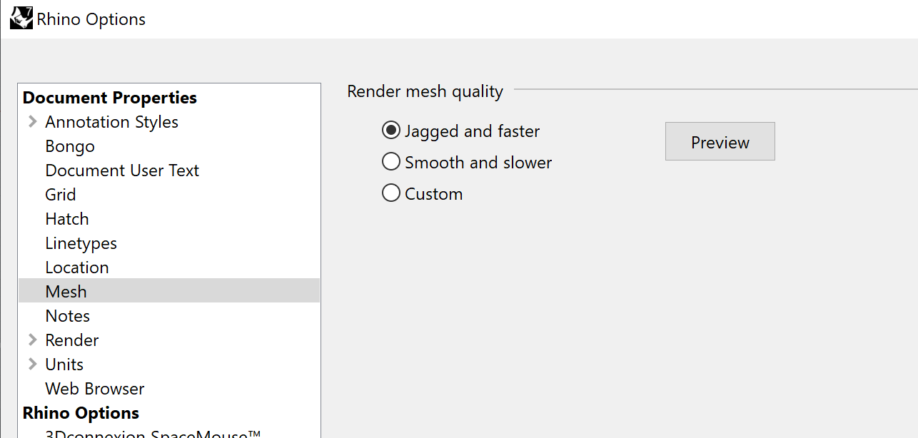
Note that these settings have nothing to do with the geometry of your surfaces - they just control how images of that geometry get rendered so you can see it.
HTH
Jeremy
Hey Jeremy,
does it appear in your model, that the circle is still not perfect but better?
I applied the detailed preview settings but when zooming really tight in i am getting a pictures which is as the one before. Where the Extrusion does not fit the circle. So i am quite sure, that rhino somehow just describes the circle with a bunch of polylines. I have the same result when lofting
Hello - please look at the links above about how display meshes work. In short the display mesh is an approximation of the geometry - this has nothing to do with what goes out in the dwg file.
-Pascal
The funny thing is though, the imported model looks EXACTLY (100%) like the displayed unperfectly round Breps. I can’t believe that that is a coincidence

It is. There are no meshes in your export file (the one you posted above anyway) so there is no way that Ansys could have gotten that info from the Rhino file. And like everyone else here has already suggested, I invite you to read up on how display meshes work in Rhino.
Hi @joshiachi,
No not a coincidence: your export settings are wrong and you are splitting the Rhino extrusion into lots of tiny curves (I emulated your settings and exported a single extrusion: on import it was no longer a polysurface). I don’t know where you are going wrong (I don’t speak German and have only used DXF once or twice).
But given that @Helvetosaur could export and reimport polysurfaces, maybe start with the 2007 Natural scheme he used instead of the one you chose.
EDIT: I don’t think 2007 Natural is right, it reimports as curves (full, not segmented!). 2007 Solids looks like the one that maintains the polysurface characteristics.
HTH
Jeremy


