I’ve always wondered what the purpose of moving the centroid out until the the angle sum is 0 degrees. I’m assuming its to get the flattest polysurface possible so the distortion is minimal after the panel is flattened. Does anyone know anything more about this?
You must ask Andrew Kudless ! I am quite sure you are right, in order to have no superposition (so piece must be done in 2 pieces) or cut (you will need some bevels), the 360° angle allows to have just foldings. More easy for the cutting and the assembly.
Thanks for asking the questions, as I make some objects from unrolling cardboard and now aluminium, this trick could be very useful to make some objects. I am on this. so each piece must unfold without overlapping, not always easy. https://st3.ning.com/topology/rest/1.0/file/get/1842132635?profile=original
Maybe going off topic now but I have also been looking for an opportunity to use a “strip” panel method like the one your image. It’s attractive to me for the same reason as the original post. Less pieces = less pain.
I’m curious about the method used. Please correct me if I’m wrong but I’m assuming you start with a triangular mesh that then is broken up into strips (is this governed by curvature or number of pieces?) After this step then you break up the piece into another set up strips so that there is connection between the pieces?
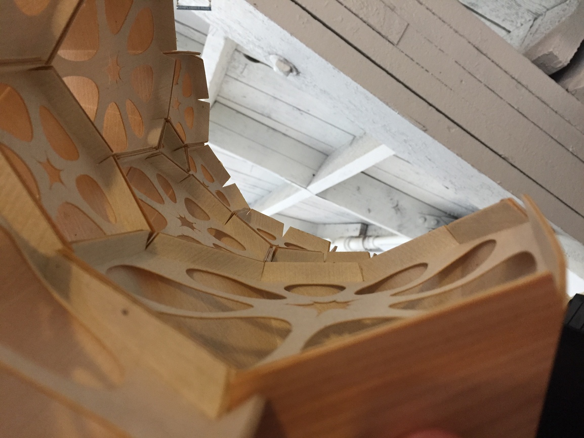
Yes, you guessed the reason for the 360 sum angle at that central node. I didn’t want any seams introduced into that panel. Anything less than 360 would have produced a missing slice when unrolled flat and required a new seam in the panel. Anything more than 360 would have produced a bad overlap and would have had to be produced in two separate pieces (so two new joints). With 360 sum of the surrounding angles, the piece can be cut flat without any overlaps or gaps. Once it is cut, it is then attached to the non-planar edge of the surrounding cell. This forces the panel to become non-planer and produced stress in the material making it stiffer when all assembled. I happen to be sitting next to an early prototype in my office so you can see in the photo below how the back of each cell is curved yet all of the edges are straight. Basically, I wanted something like a patch surface that was developable and this iterative method arrived at a pretty good solution. Introducing a seam would have stiffened the material at that seam, added more labor to the process, and made the resulting surface less visually clean.
Nice capture, @akudless1 and thanks for the detailed explanation, which tool you use to calculate the 360 sum? with an evolutionary solver could be one way easy but it’s pretty slow, @DanielPiker this could be solved with kangaroo?
It is quite easy to calculate but most of the time there is 2 solutions. So I choose to use curve intersection of RhinoCommon to make the calculations.
 /// <summary>
  /// Return points which have a 360° sum angle with the polygon points
  /// </summary>
  /// <param name="polyline">A closed polyline</param>
  /// <returns>The line</returns>
  public List<Point3d> GetFlatCenterOfPolyline(Polyline polyline)
  {
    //Center of polygon
    Point3d center = polyline.CenterPoint();
    //Plane used to have a normal
    Plane plane = Plane.Unset;
    PlaneFitResult plfit = Plane.FitPlaneToPoints(polyline, out plane);

    //Calculation of a typical length
    BoundingBox bb = polyline.BoundingBox;
    double length = bb.Diagonal.Length / 4;
    Line line = new Line(center + plane.ZAxis * length, center - plane.ZAxis * length);

    //For many points on a line calculate the angles sum
    List<Point3d> points = new List<Point3d> ();
    for (double d = 0; d < 1.0; d += 0.01)
    {
      points.Add(new Point3d(d, GetAngle(polyline, line.PointAt(d)), 0));
    }
    //The angle sum is a curve with the line parameter in abcisse (Y) and the angle sum in ordinate (Y)
    Curve curve = Curve.CreateInterpolatedCurve(points, 3);
    //A line at ordinate = 2 * PI
    Line line2 = new Line(new Point3d(0, Math.PI * 2, 0.0), new Point3d(1, Math.PI * 2, 0.0));
    //The intersection calculation
    CurveIntersections ci = Rhino.Geometry.Intersect.Intersection.CurveLine(curve, line2, 0.0001, 0.0001);

    List<Point3d> output = new List<Point3d> ();
    for (int i = 0; i < ci.Count; i++)
    {
      output.Add(line.PointAt(ci[i].ParameterB));
    }
    return output;
  }
  /// <summary>
  ///  Calculate the angle sum from vector from the point to the polyline point
  ///Polyline must be closed
  /// </summary>
  /// <param name="polyline"></param>
  /// <param name="point"></param>
  /// <returns></returns>
  public double GetAngle(Polyline polyline, Point3d point)
  {
    double angle = 0.0;
    for (int i = 0; i < (polyline.Count - 1);i++)
    {
      Vector3d v1 = polyline[i] - point;
      Vector3d v2 = polyline[i + 1] - point;
      angle += Vector3d.VectorAngle(v1, v2);
    }
    return angle;
  }
``