Hoping I can get some advice – I’m trying to model a flexible attachment that will fit over a moving joint (similar to a cv boot). The part will have a flexible cv boot form connecting between two “cuff” surfaces which will mount to the device.
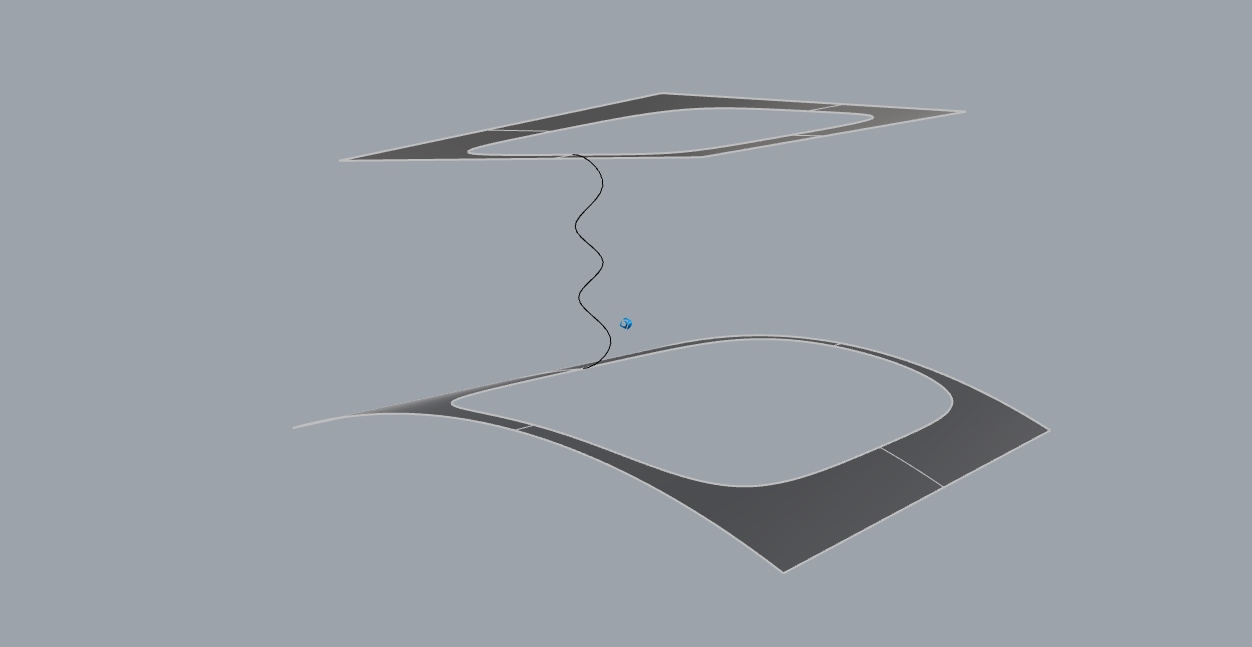
I got the profile curves for the edges by getting dimensions and using dupedge from a reference model of the device. I then rebuilt the curves I duplicated to use as fewer points while keeping deviation under about 0.01”.
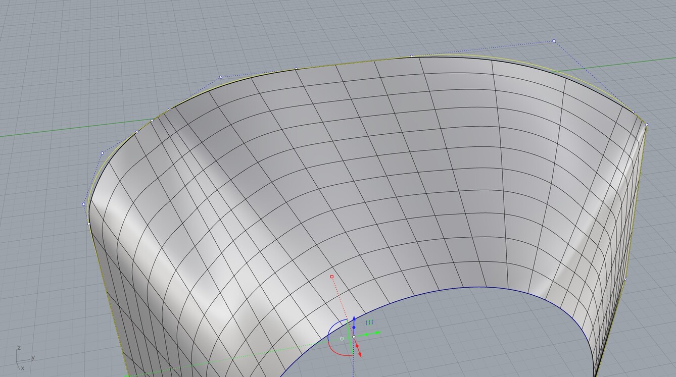
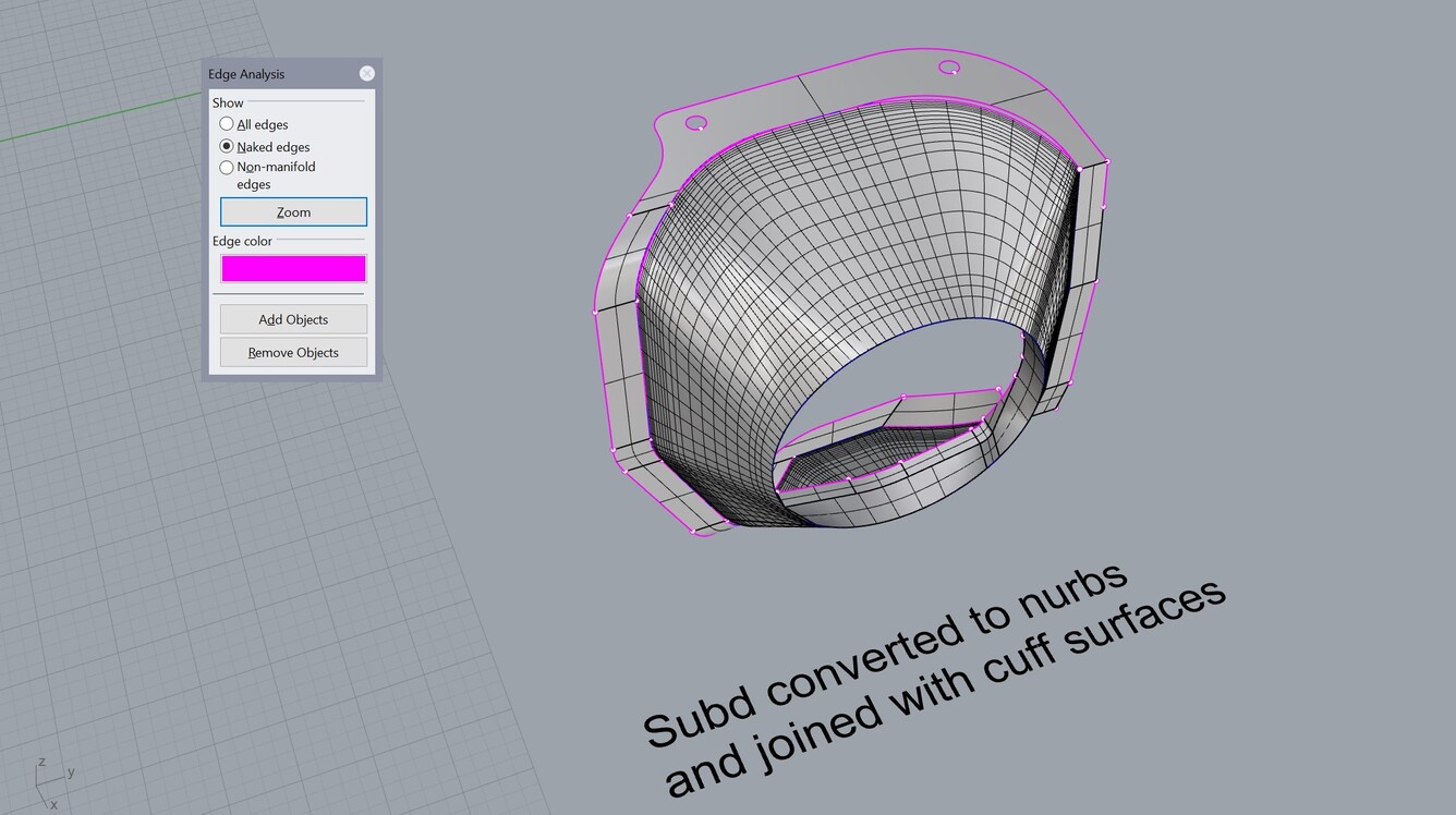
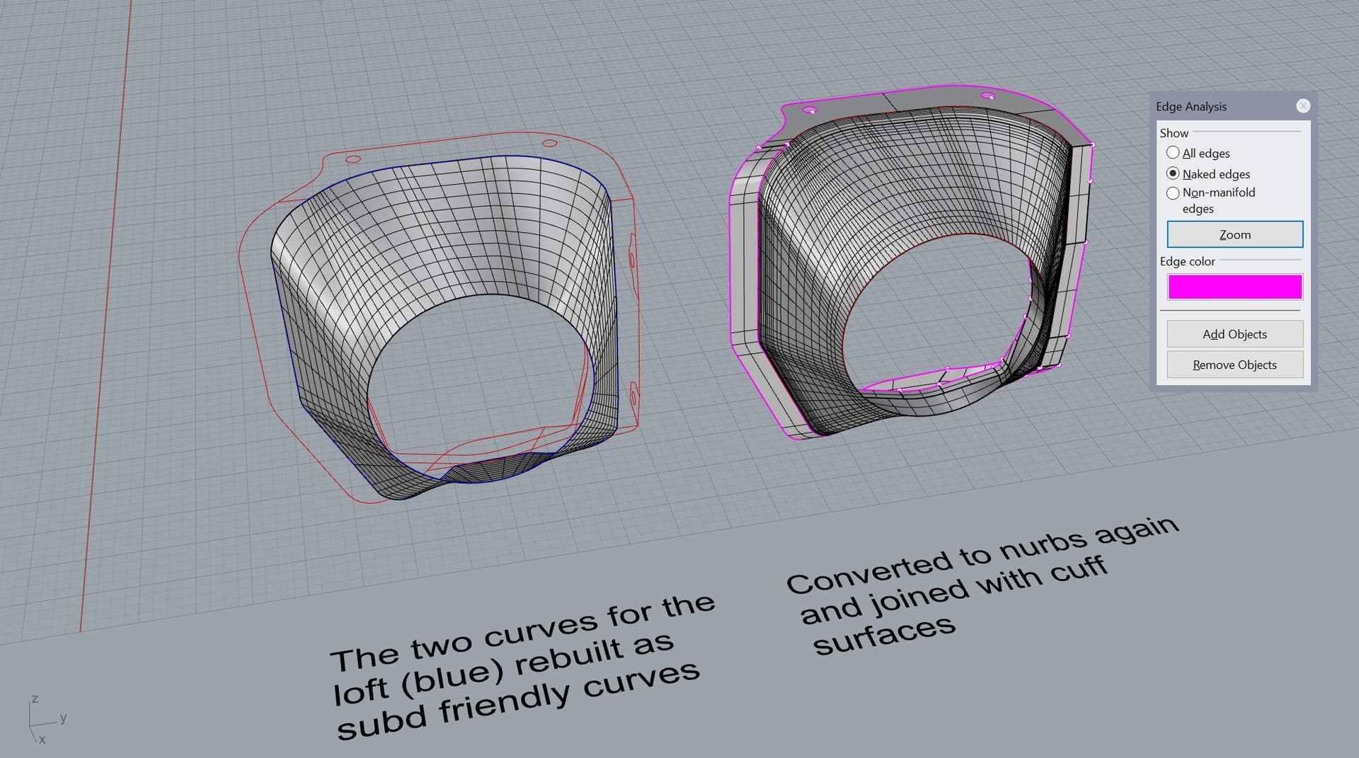
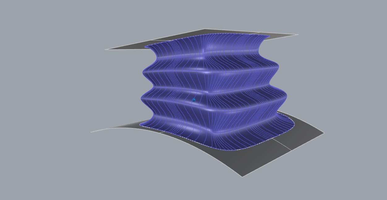
I’m guessing subd would be ideal to use for lofting/bridging the two cuff surfaces as it’s an organic shape that I want to be able to subdivide and sculpt folds into. I used subdloft to do this – the problem is matching it up with the cuffs (which I made with normal nurbs surfaces). I’m able to adjust the subd edge manually, align it to the profile curve, add creases to the vertexes where there are straight segments and corners, etc. The closest I got was rebuilding the two profile curves as “subd friendly”, but converting to nurbs and joining to the cuffs still leaves many naked edges.
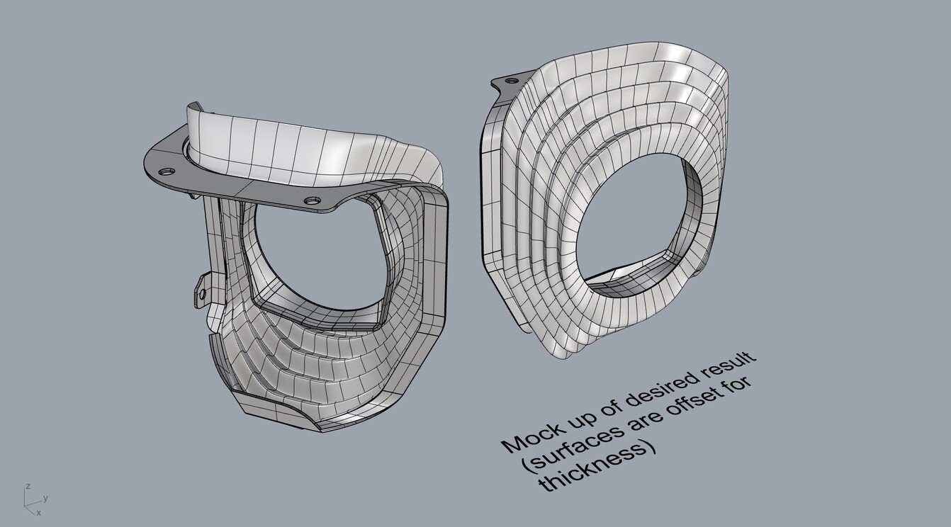
Does anyone have any recommendations on how to do this or a different workflow I should be using? I included mockup of what I want it to basically look like (I’ll have to join the cuffs and loft together and add thickness to it for 3D printing).
Thank you for the help!
TLDR – I’m trying to create a subd surface that will act as a organic/flexible between two other polysurfaces, but I’m having trouble figuring out how to get edges to match up accurately (to avoid problems with joining together into one piece).
Hello - can you post a file with the object and the input3, or send to tech@mcneel.com with a link back to this topic in your comments?
Oops- never mind I see the file.
I don’t know what you do, design wise, when the distance between the ends of the boot vary so much - there must be best practices for how to arrange the folds in cases like this but I have no idea…
I feel like with subd I can just adjust the edge loops until the folds look right - the problem I’m running into is just transitioning from the subd surface to a normal nurbs surface (having the edge of the subd match with the outer profile curve accurately).
I might be better off just constructing the whole thing (loft and cuffs) in subd and just adjusting until it looks close enough to the dimensions of the device to fit? Thanks anyways.
Be aware that SubD surfaces at edges and creases always have zero curvature in the direction perpendicular to the edge or crease. That is how the math works for SubD in Rhino.
An alternative to building the SubD surface would be to create a curve with the appropriate waves between the edges of the polysurfaces and then Sweep2 to create the cuff. You may need to use the Chain option when picking the rails.
Thanks David. I tried just using my subd surface as a basis for the folds and projecting some lines onto it to use as sweep sections - closing the sweep didn’t really work (looked like it was having problems lining up the sweep sections and not twisting them (had to use multiple since the folds are smaller on the sides). However network surface works pretty well to.
Thanks Kyle - I’m not familiar with the pipe trim method but will definitely give it a try. I looked into blend surface earlier and was just using offset curve on surface for the outer edge of the boot to give it some space to work. - The pipe method seems like it will work better. Thanks for the help!
I like the pipe method because it’s pretty quick, especially if you chain the edges of the surface edge you are going to pipe- In cases where the edges are less than awesome, pipe them anyways, then use the smooth function of the moveuvn command to “untie” messy control points of the resultant pipe-
Sorry for the lack of feedback – the pipe trim method worked well, though I’m running into issues with offsetting/adding thickness to the whole thing for 3d printing. I opened a new topic for this. Thanks again!
Keep in mind, if you are just 3d printing, you can mesh teh part and then offset the mesh with thickness and the “solid” option and not have to work thru making a nurbs offset.