Making plywood miters. Petras' Ngons is almost the holy grail

As a person who does a lot of work with CNC cut plywood, when I first saw @Petras_Vestartas’ example for his offset planar component, I was pretty excited.

Petras’ example takes almost any closed polyhedron with valence=3 vertices and can instantly transform it into mitered parts for each face. And while Petras warns that it won’t work with higher valence vertices, sometimes it does work for 4, 5, 6 or more edge intersections at a vertex.

I used the RhinoPolyhedra plugin to try to break Petras’ example, but the component is pretty damn robust. I love it! Here’s my definition for testing it:Ngons almost holy grail miter-izer.gh (449.0 KB)


The example above has some valence 4 vertices that work. When testing I did a lot of very close zoom-in inspections. In some cases, like with geodesic triangle spheres, the errors are tiny, in the .001-.005 unit range. When a high valence causes a failure it looks like this:

Could this be detected with a script?

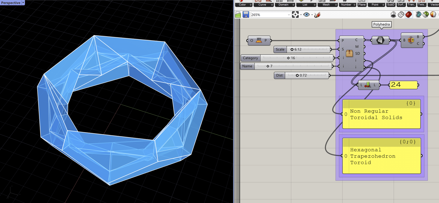
That said…There are some pretty wild and unexpectedly cool situations in which the code works perfectly! Both of these are buildable using mitered sheet goods, all needed parts as individual breps.

There is also one minor bug: I found a few situations where, on non-convex faces, if an interior triangle mesh edge on a polyhedron face is close to colinear with an exterior edge of the face, the nGon conversion fails and produces an error in the final output. What’s interesting to me here is that different scale settings on the polyhedron produce different errors. Is this a tolerance issue?:

There is also another minor bugs sometimes with non-convex faces, also depends on the object scale:

One last thing: These NGons components are thoughtfully made so that if you explode the parts they output, the original polyhedron face is item zero, and the parallel offset face is list item one. This means no matter how many faces an output part has, you have easy access to them to assign planes for orienting.

I love this thing! Curious as to other people’s experiences and thoughts about what I wrote above, but mostly just wanted to post this in appreciation and so other people can play with it.

7 Likes

Thank you for kind words and it is great to see you working on these timber plate geometric issues;)

I will take a look at your code once I am on pc.

I was mainly working with hexagonal geometries and did not think it works for n valence. Normally it should not. Is it also planar if you scale up the geometry i.e. 100 times?

For polygonal meshing, there are two ways currently to triangulate a polygon. 1) star method by placing vertex at polygon center 2) standard ear clipping minimal triangulation. You can change triangulation by right click on component from polylines. But maybe it has some exceptions as you pointed out.

This is an old post from grasshopper3d, that I still do not know how to solve:

4 Likes

How do you attach pieces like this? For a regular polyhedron, you only have a few dihedral angles to consider but even if you stretch it slightly, it multiplies the number appreciably. Would Ngon help with designing the connectors?

I did barely any work. I just stuck two plugins together and put a basic display on the end, lol.

What I think happened with the situations where it works on over 3 valence is maybe symmetrical crease parts work no matter what? In some cases, like geodesic triangle spheres, some vertices work and some don’t, and the ones that work are the ones where all the triangles that meet are identical. With that first propello solid, I don’t have an explanation. In some cases, especially with high numbers of faces, the errors are probably just smaller than document tolerance, which, for construction purposes, is fine.

My idea was to use a 5 axis CNC to cut notches for splines or tenons into the plywood. Just need to find a way to reliably place simple toolpath geometry in the right place and then orient it all to the Cplane together.

Alternatively, for simpler shapes: masking tape on the outside seems, and just carefully glue it up. And with a 5 axis CNC it may be possible in some cases, using a sharp angled vee bit, to actually do miterfolds, where you leave the last 0.007 inches of the material intact.

1 Like

Re: the old post for closed planar volume offsets, I’ve been trying to figure that one out, too and I am much much less educated about math and geometry and code than you are. I have a manual method that I use to do it that feels very algorithmic to me now, and I wonder if it can be translated into code or if I’m actually making some arbitrary human choices along the way.

I will try making a separate post that goes deeper into how I do it, how various conditions are resolved, and I’ll see if I can ask questions that lead us in the right direction. I’m sure it’s not anything that someone else hasn’t attempted already, but it’s been on my mind a lot. Seems worth typing it up.

For manufacturing inspiration, have a look at this old plugin…

TIMBER PLATE STRUCTURES

It generates a sort of dovetail along the edges.
image

I’ve spent some time trying to work out how to make timber frame triangles with mitred edges for making geodesic domes or triangular mesh structures. You are right that it works when there is a rotational symmetry around the node. When there isn’t you end up with either a gap or a collision right in the corner which can sometimes be ignored for manufacture as it is often just a case of removing the edges on the nodes that don’t work.

I can’t remember the science but it could be down to whether the mesh is “conical” or not… i.e. do the mesh normals at the vertices all lie on a common cone. Perhaps this is the condition that must be met to make the corners work?

Kangaroo can make a mesh conical.

3 Likes

As I said in that old gh forum thread- for the general case where the vertices have valence greater than 3, even if the faces are planar, there won’t exist any vector along which you can offset the vertices that gives planar faces parallel to those of the original faces.

If you do offset all the faces by the same amount, usually they will not intersect in a single point, so each vertex in the original will turn into multiple vertices in the offset.

For valence 4, the specific condition the mesh needs to meet is indeed for the faces around each vertex to be tangent to a common cone.

For general freeform shapes you need to do some optimisation to meet this condition.
Here’s an example that lets you deform a mesh, then make it strictly conical and planar, and calculates the offset so that every solid panel has parallel planar faces of the same thickness
conical_offset.gh (27.1 KB)


(see also these old threads 1, 2)

7 Likes

The collision at the corners, and creating some sort of algorithm for deciding which get trimmed, is what I was talking about above when I said that in my manual process for dealing with 4+ valence miters, I think I’m following a fairly algorithmic process that might be able to be replicated in grasshopper.

It’s clearly more complicated than I think, though, if nobody’s cracked it yet. And it seems like it’s the important thing to crack, because if we want to be able to use any planar brep as input, that’s the only way.

Because a miter is by definition an even division of a crease angle, maybe there’s something that could be done here with plane intersection components? Or maybe there’s a way to run through multiple iterations of possible solutions and pick the ones certain criteria, like the most convex outline on the inner faces?

This paper nicely describes the solution for if you’re happy to accept not having a 1:1 matching of nodes between inside and outside:
https://www.researchgate.net/publication/283264212_Exact_face-offsetting_for_polygonal_meshes

5 Likes

Thanks! Hopefully my high school math brain can figure it out (not optimistic, but I’ll try).

I’ve never come across an application where it was essential for me to have 1:1 matching of nodes inside and out. I build interiors, sets for special events, and fine art. Most of the time one side of what I make doesn’t even get paint, :joy:.

2 Likes

I’ve thought a lot about working out how to deal with those collisions… For structures with only slight curvature the collision is tiny and, if the structure was made out of timber, would just need the sharp edge knocking off with a sanding block. It would still be nice to know which corners and precisely how much to knock off though. It is slightly beyond my ability at data management on GH though! I bet someone could do it in 3 components but not me. Yet!

The other idea I thought of was to put a cylindrical dowel at each node… I.e. knock all the corners off during panel manufacture and then after assembly, with a jig, drill a dowel hole at each node that can then be plugged and finished with a dowel. It’s a bit like sweeping the problem under a rug and a shame not to have a perfectly joined structure though. Also, its only really a solution for slight curvature!

When I get R6 I am going to experiment with Daniels solution that makes the mesh conical and planar. The link he posted above looks interesting too.

1 Like

Regarding timber joint. We had lots of discussion in past years how to continue with the joinery development. The idea was not to rely on one structural morphology but rather start from element to element joinery relation, whether it is a beam, plate or raw-wood. There always will be a design model but at the scale of the joints it is possible to create a generic code to avoid another pile of code just to model end-end, side-end, side-side or half-lap joints.

On one hand you might say, if you develop joints locally without relying on fast mesh data-structure, your code will become slow, but this prevents from making modular joinery methods and reuse code in general. In the end we could apply fast collision searches i.e. bounding box, line-line, curve-curve, face-face, plane-polyline to speed up the process. And there were tons of help from McNeel forum to help me through the process. For sure, every project has it`s own specificity but at least we could start not from scratch.

I had to help for developing further old projects that were already published and learn from new ones.


Then gradually we developed ideas and code for local joinery conditions. The goal is that a user could design a model using basic elements and then a solver would create joints. And then when it comes to teaching, students could at least get research inputs for more common projects. For those, we had difficulty before because the only answer was to “code it yourself” which resulted in Grasshopper spaghetti or C# spaghetti or use CadWork. An then you need to consider fabrication tool-paths especially for 3d joints because there is a tight relation between robots or cnc machines and those geometries. While these are just pictures, we had recently made a workshop where I could already apply some methods for teaching.


10 Likes

Do you know if Daniel open-sourced any of his research ? It would be great to have something similar for Rhino users.

I don’t believe they did (we’re talking about Daniel Hambleton, one of the authors of the paper I linked in my last post, for anyone reading confused by the multiple Daniels!), but agree it might be a nice thing to have in Rhino.
I remember when they presented it, I thought it was beautiful work, but wasn’t so keen on the illustrated application. For steel beam and glass structures I think complex welded nodes with all those little extra triangles would be a bit messy, and much prefer to change the geometry so the beams can meet in a single clean axis.
For timber plate structures though, where those faces are internal interfaces, it could be great.

1 Like

Hi,

I had a little bit of time to go through your definition @Max3 .
To have a bit safer solution I added the method you used in Python as a component to add planar ngons and then simplify the mesh topology, in case there are unnecessary vertices, which I suspect was causing a few issues. Also I added mesh loft with holes, which works better that the standard loft component (now it is not relying on 3rd party libraries and is not crashing as before):

I had to update the plugin, because I found a few bugs, new version 2.4.3:

4 Likes