Make a swirl opening between two or more surface

Hey,
I am now trying to make something like this. I am most interested in making those ‘swirl connections’ wherein the bottom floor and the floor above become connected.

I cannot find a workflow of how to do it. Do you might have an idea?
Thank you for your answer
:smiley:


problem create access swirls between surfaces 01.gh (19.4 KB)

1 Like

I wonder if you could define some basic shapes, and then use curve offset and between functions to get those parallel lines.

Perhaps also, you could draw/define curves that would be projected or pulled onto the surface. Depending on the shape, these might be lofted.

Topology-wise, I would try to figure out if it’s really a single surface, with two holes, stretched through.

It’s kind of like a topomap.

Or the Belgian Waffle from Burning Man

1 Like

My guess would be that the underlying geometry was modelled by hand and the new topology generated with particles/agents. I had a university seminar headed by Stuart-Smith about two years ago, and it was all about particles flowing along or over various forms, thus generating trails.
We didn’t have access to the intricate parts of his particle engine though. It was some kind of protected, compiled Processing library, if I remember correctly, and the course was rather boring and unintelligible.

Producing this in GH, starting from two mesh planes, seems rather complicated and time consuming - if not impossible - to me. You’d have to come up with a monstrous script that would somehow shape, erode, morph the planes with internal and external forces and probably millions of particles, only to get an unpredictable form that could be modelled quite quickly in ZBrush, Maya, Modo, Max, C4D, etc. and that you could apply your existing particle scripts to.

The topology of your above reference seems to be derived from particle trails. At first glance, it looks like a coherent mesh, but if you look closely, it rather seems as if the individual particle trails are carefully produced with a certain regular offset to adjacent trails. This would make it a breeze to produce mesh strips from the trails. These strips could then thickened by extruding them, making it seem as if the structure was a single mesh.
Note how the mesh tessellation seems to mirror the trail direction. Each mesh face seems to be hexagonal or composed of two quad faces.

Maybe you are fortunate enough and one of the GH gods descends upon this discussion and blesses you with a more divine workflow. :pray:

1 Like

Look! I have made it something (dendro). It is not sexy, but it looks like it. I now have to make it sexy.

I can make it more sexy with different curves, but is should mostly be done by the smoothening I guess. What do you think?

problem create access swirls between surfaces 02.gh (34.8 KB)

It depends!
Let’s say this is your final output that you don’t want to change the topology or form of anymore, then you should be fine!
However, if this should function as a base mesh to other processes (particle or climate simulation), you are probably in trouble. It would be much better to have a simpler quad mesh as a single surface without thickness. It would be faster to process and more straightforward to work with or change.

Here’s an example:

09

example.3dm (3.2 MB)

1 Like

I could use that twix in between the two surfaces and cutting a hole with it somehow. It will make the surfaces connected and at the same time create a by-pass from platform one to platform two.

Did you do this in Grasshopper?

Nope, quickly in Maya, also starting from two mesh planes.

1 Like

I am trying to find a way to morph meshes like you did, but then in Grasshopper.
I do not find anything.
Are there might other keywords you know about?

Are there might other keywords you know about?

Polygonal Modelling :smiley:
as said a few times, these base forms are usually just modeled as polygon meshes. Will take you a few minutes in something like Maya, Blender, Modo, T-Splines, etc.

1 Like

This is somehow similar to it. But, how did s/he go from curves to a mesh? I cannot find the component for it.

Do you might know which component made her/him do ‘going from a polyline to a mesh?’

In rhinocommon, there is method for transforming closed polylines into meshes.

import Rhino.Geometry as rg

mesh = rg.Mesh.CreateFromClosedPolyline(pline)

In Kangaroo, you can use Soap Film in combination with TangentialSmoothing to relax the mesh.

1 Like

I tried to mimic the ‘soap geometry’ in the image.
Do you know if there is something else similar to the SoapFilm component?

problem soap bubble 00.gh (10.1 KB)

Since, you forgot to internalise your polyline, I couldn’t test it, but this should work:

problem soap bubble 01.gh (12.8 KB)

You need Kangaroo 2 though!

I now internalized it. :slight_smile:
I checked if it is closed, it is closed.

problem soap bubble 02.gh (11.8 KB)

The GHPython component doesn’t seem to output a mesh, if the input polyline it too distorted. I changed it a bit and now it works. The problem with the distorted polyline might be caused by polyline segments that would produce self intersecting mesh parts (?).

problem soap bubble 03.gh (13.6 KB)

1 Like

Mesh workshop
This image from mesh works Berlin workshop

Meshworks Berlin

Projects, Teaching

Type Design & Fabrication Workshop
Tools Laser cutter, pop rivet guns
Date 5th – 7th, 12th – 13th Aug 2016
Location Fab Lab Berlin | DE
Tutor Agata Kycia & Patrick Bedarf
Participants Maria Selkou, Natalie Peter, Kai Peter, Charlie-Camille Thomas, Romana Scholz, Werner Budde, Anna-Amalia Gräwe, Park Geun Woo

intro01

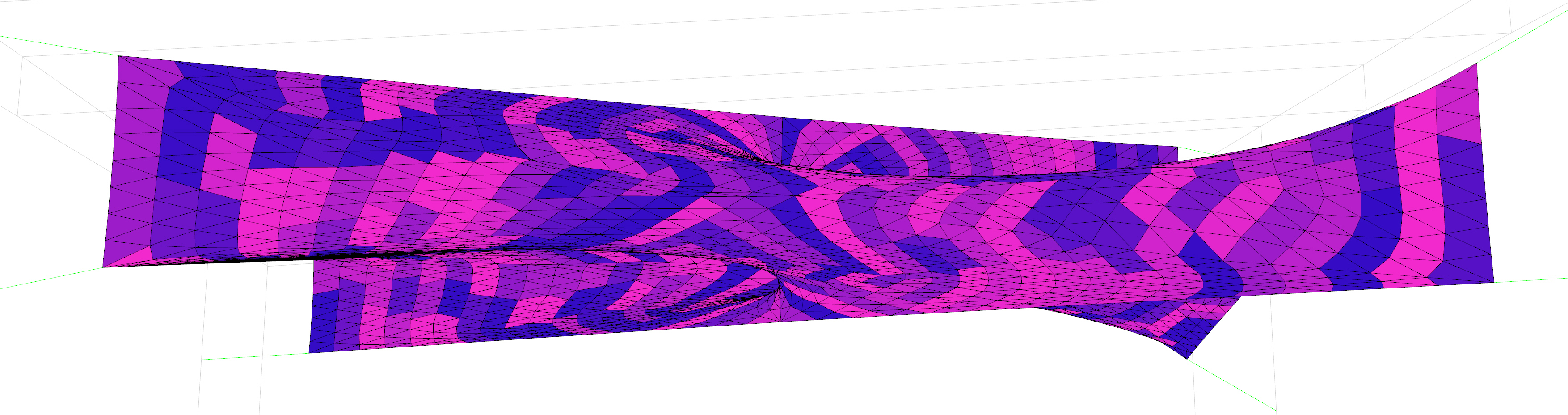
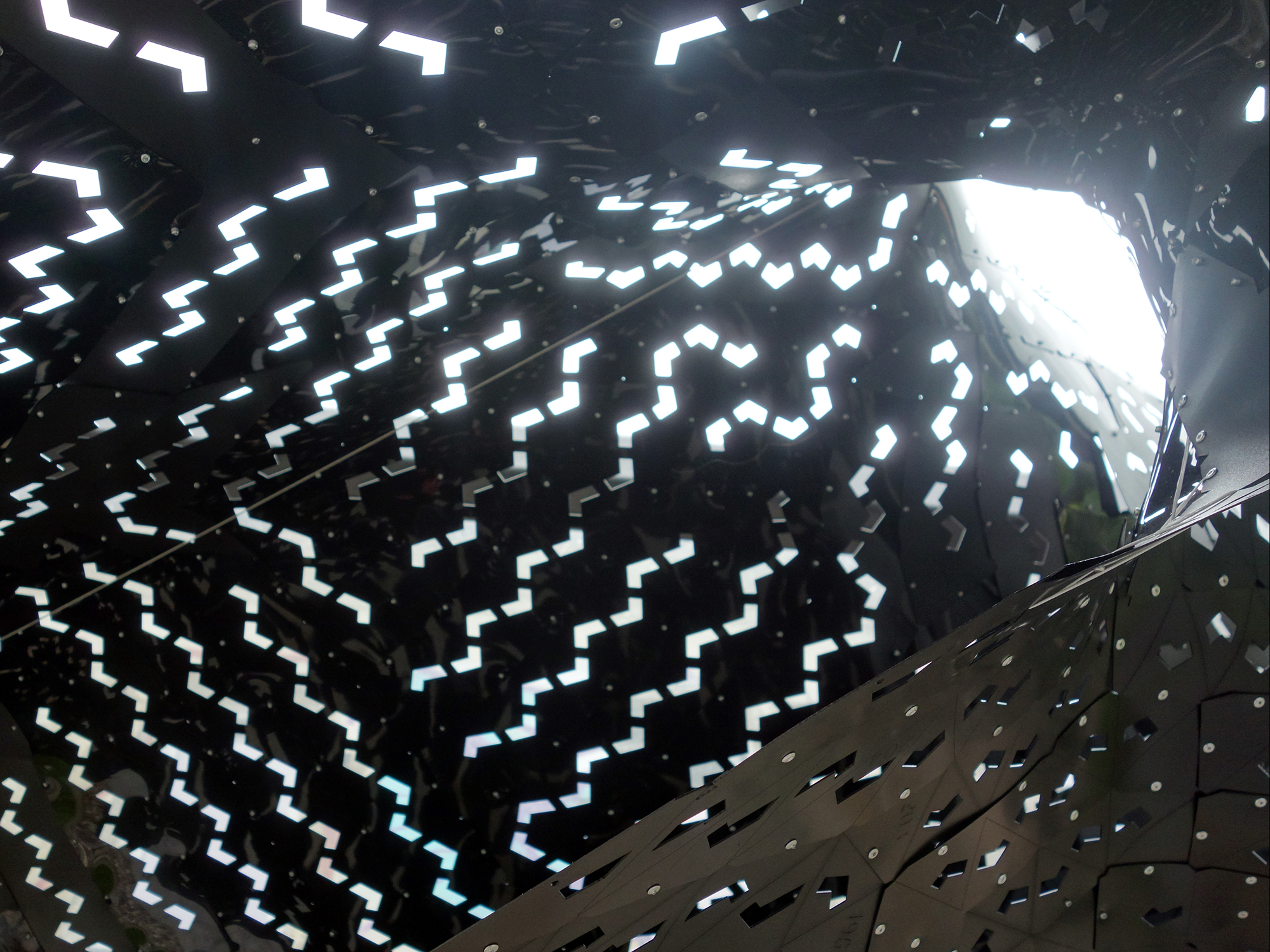
MESHWORKS BERLIN builds upon previous workshops investigating complex mesh topologies and fabrication assemblies. The five day event was tailored for the Fab Lab Berlin community of design and fabrication enthusiasts and provided quick paced introduction to Rhino/Grasshopper with its particular plug-ins Kangaroo, Ivyand Weaverbird, full workflow of parametric design and simulation as well as fabrication planning and execution of a full-scale spatial installation. Hereby, the particular focus was put on force-based form-finding design of a convoluted geometry, which could be assembled of lasercut components from 20 m² black POM sheets (0.8 mm), pop rivets as well as steel cables and clip connectors. Consequently, the workshop was structured in two consecutive weekend blocks, with a separation into (1) computational design accompanied by lectures, technical training sessions as well as material testing and (2) fabrication and assembly.

img_7176

mwb_groupwork

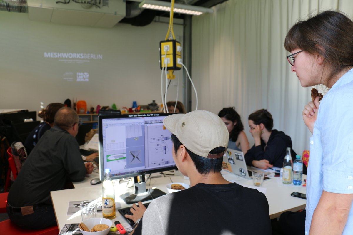
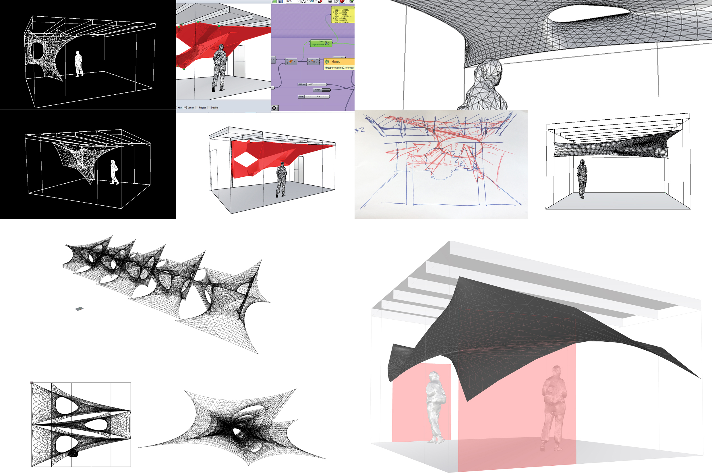
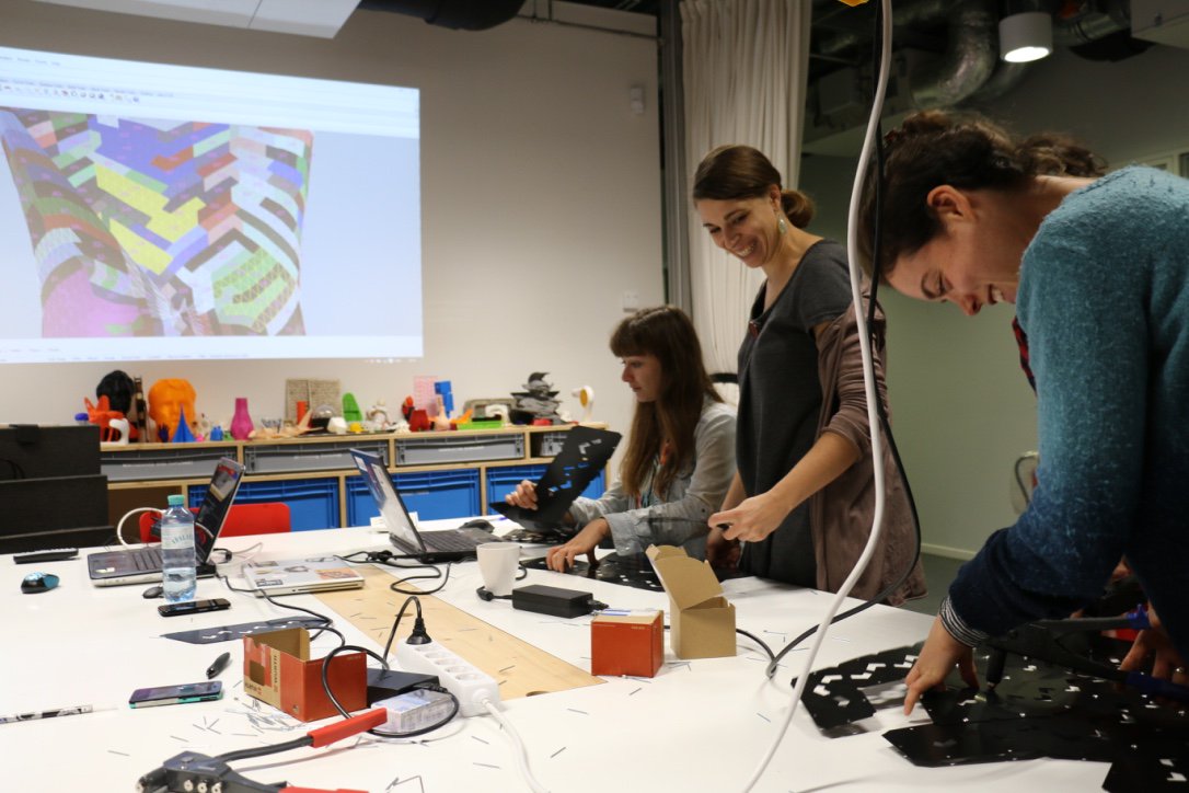
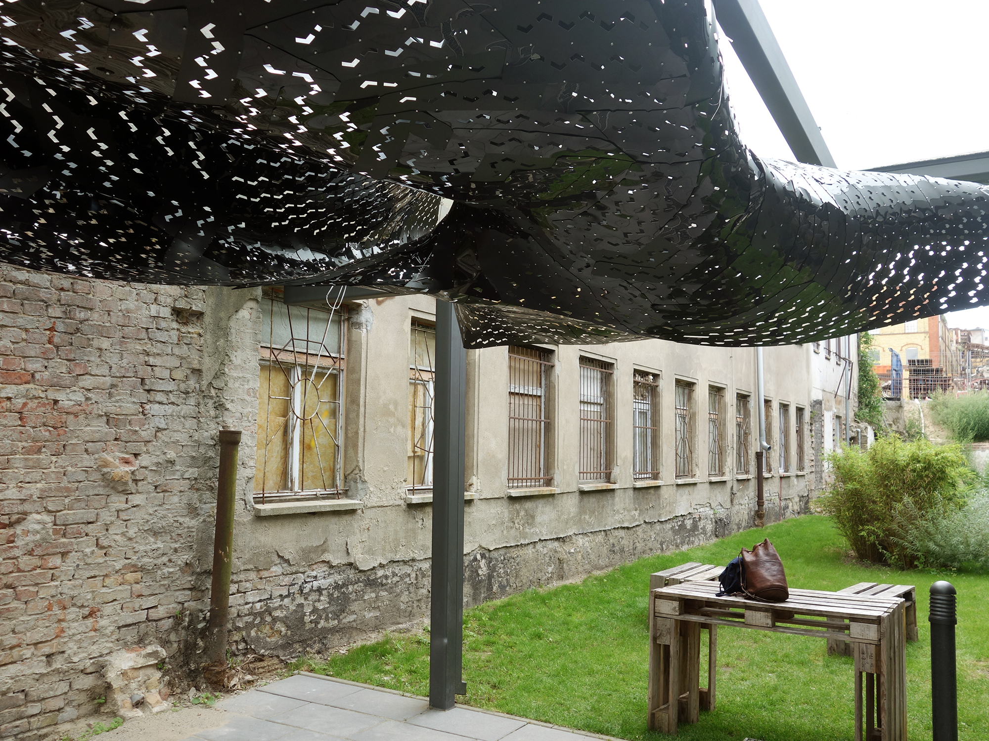
Force-Based Design During the first weekend participants were introduced to computational form finding methods and fabrication oriented geometry discretization. After initial studies on possible site interventions the Kangaroo physics engine was utilized for mesh relaxation based on low-poly input geometry. These models were evaluated and optimized regarding their spatial qualities and performance of material consumption, laser and assembly time. A democratically voted chimera of each team’s features was finalized for further processing.

10

09

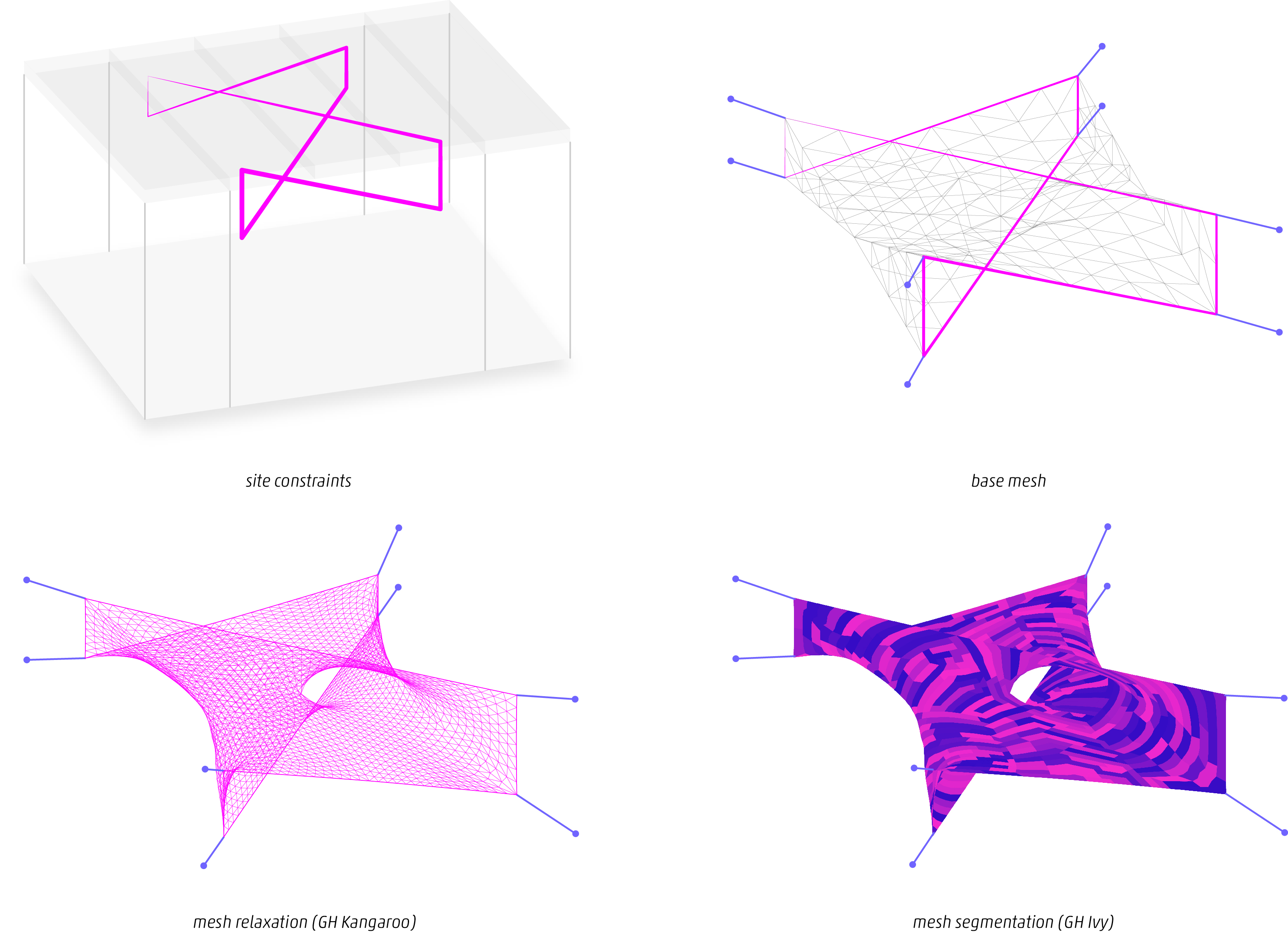
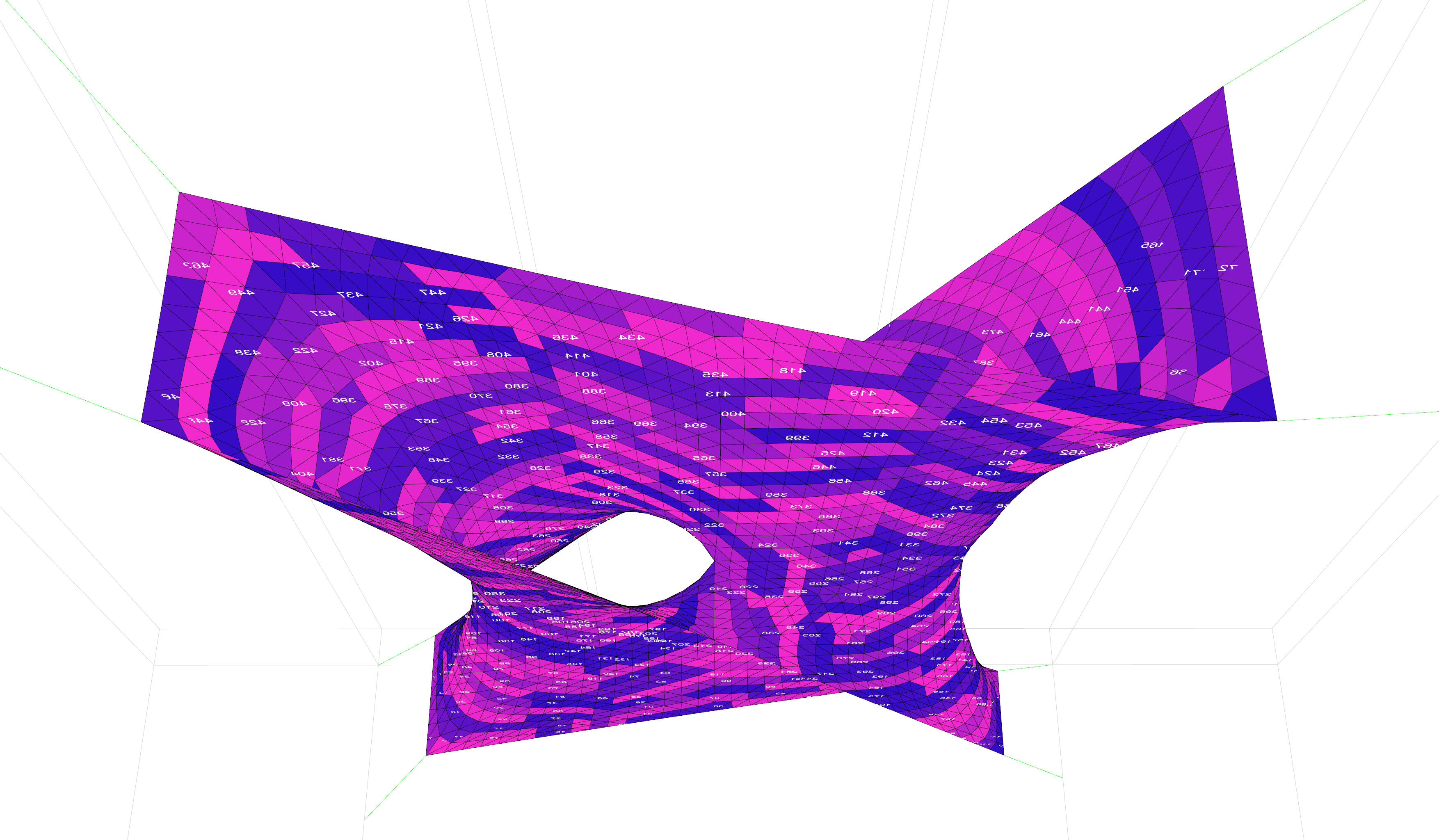
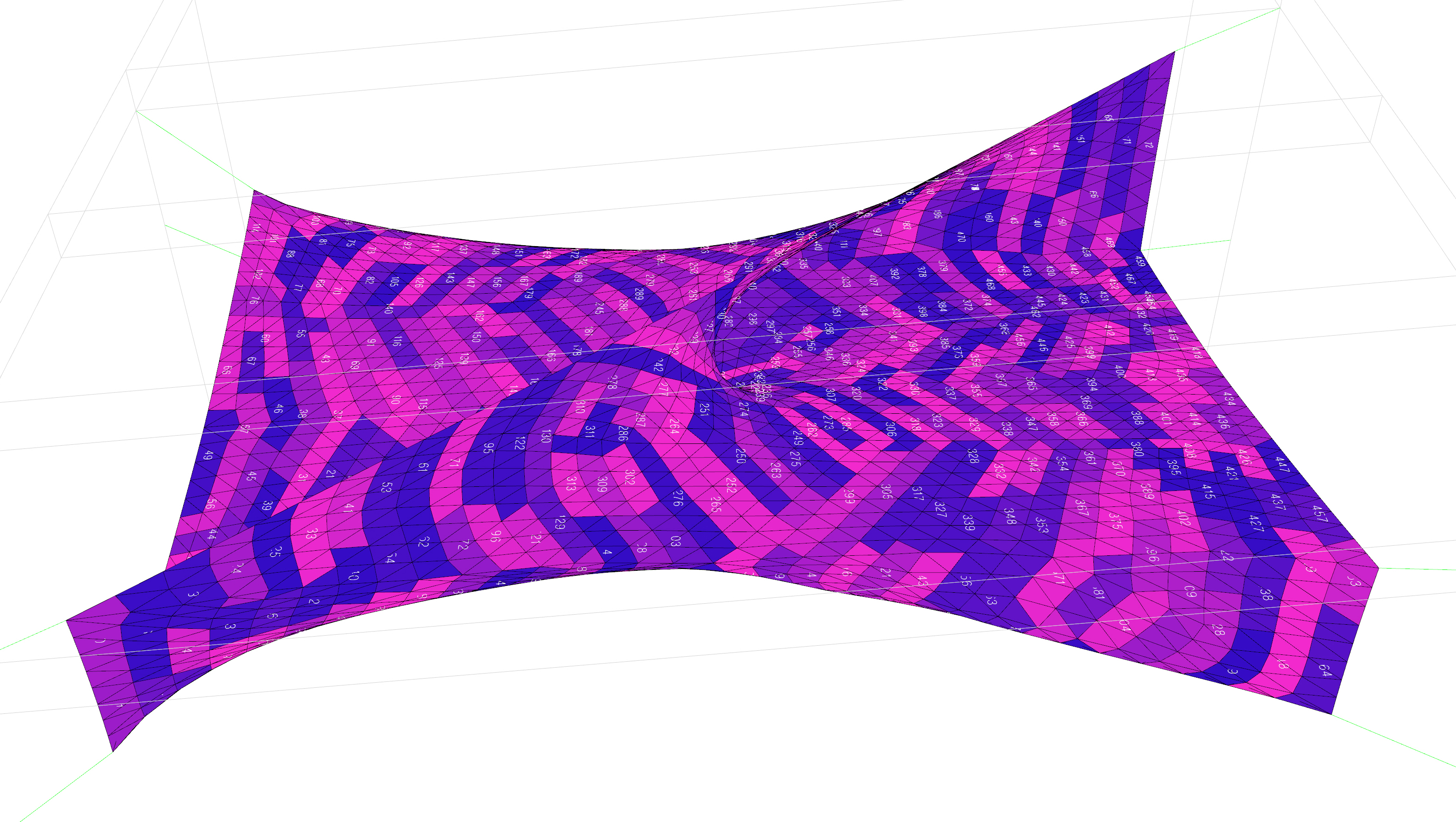
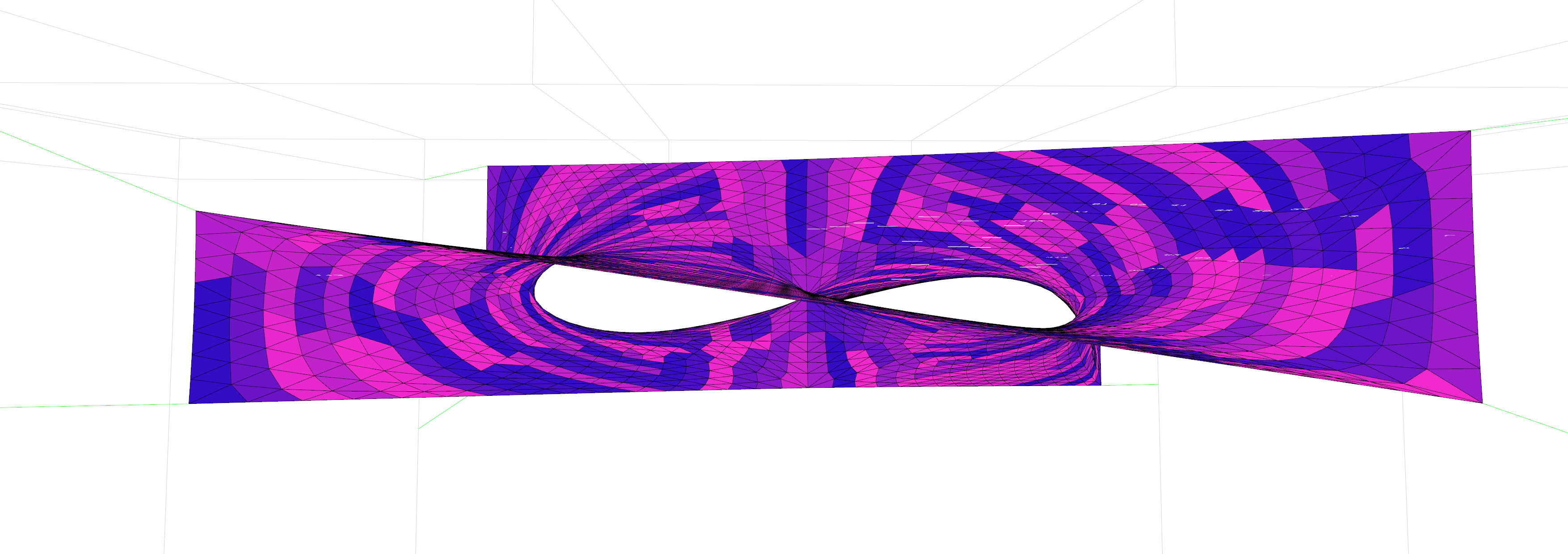
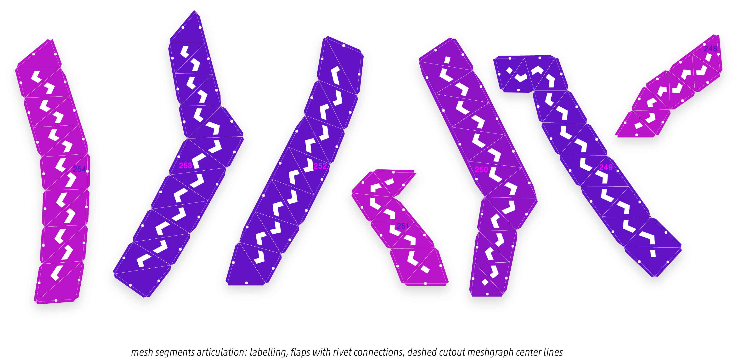
Geometry Segmentation Further mesh geometry processing involved unrolling based on primary and secondary segmentation with the grasshopper plug-in Ivy. After a short introduction, participants iterated through various segmentation strategies by trial and error in order to develop an understanding how each mesh walking algorithm unfolds on their geometry. Finally a strategy was chosen based on machine dimensions and material system properties. In a last step the segmentation strip layout was designed, which comprehended labelling, connector flaps and cutout meshgraph center lines.

img_7328

img_7327

img_7287

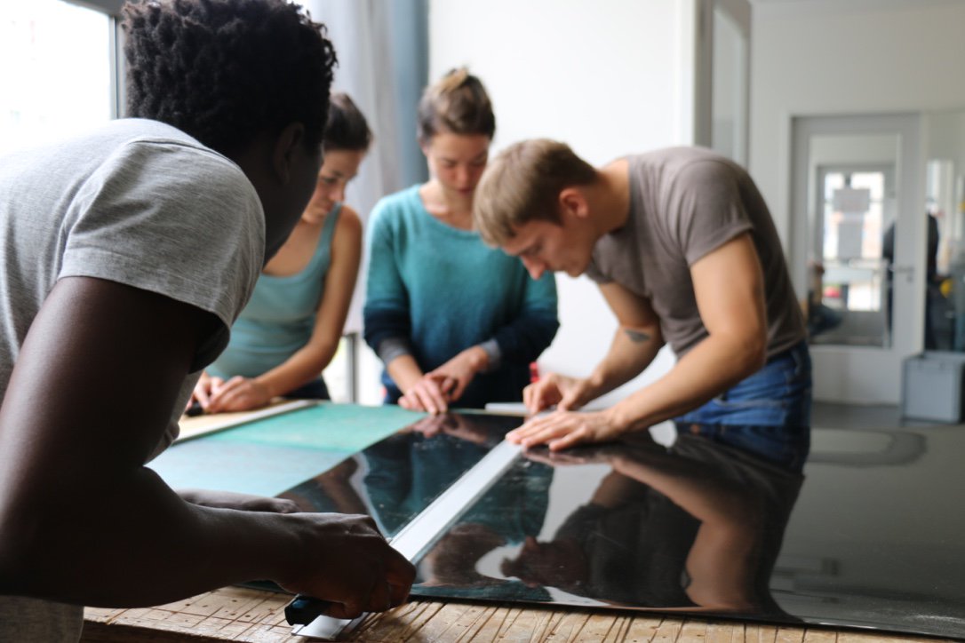
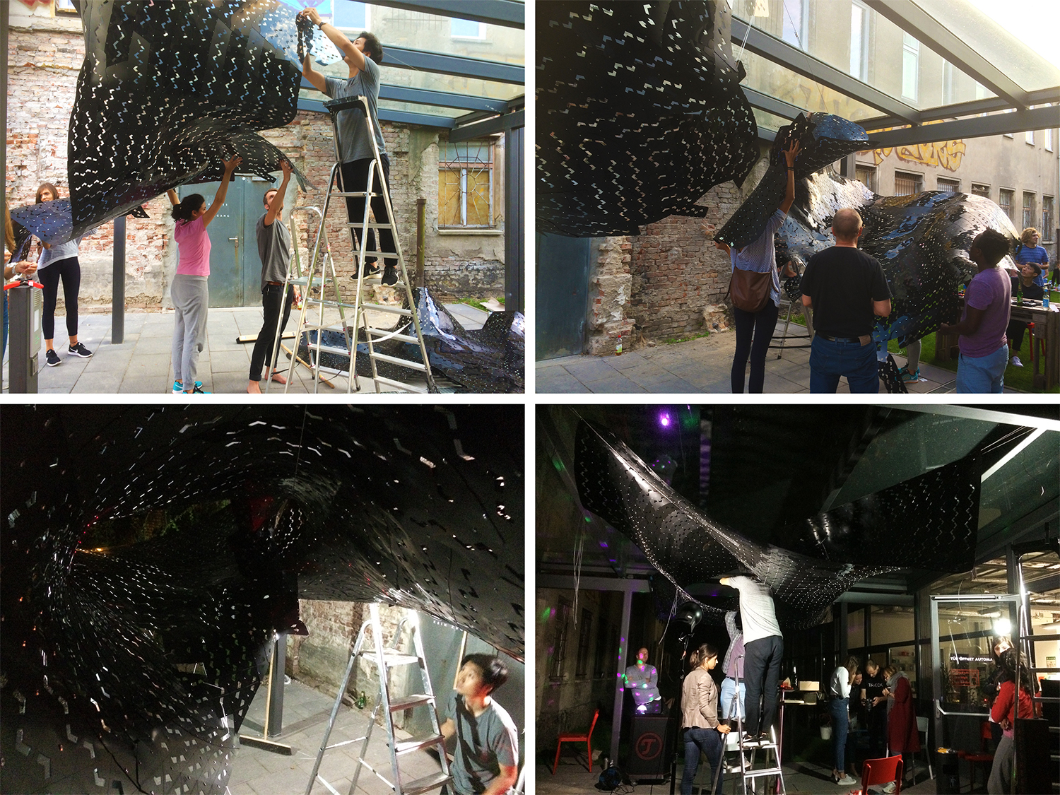
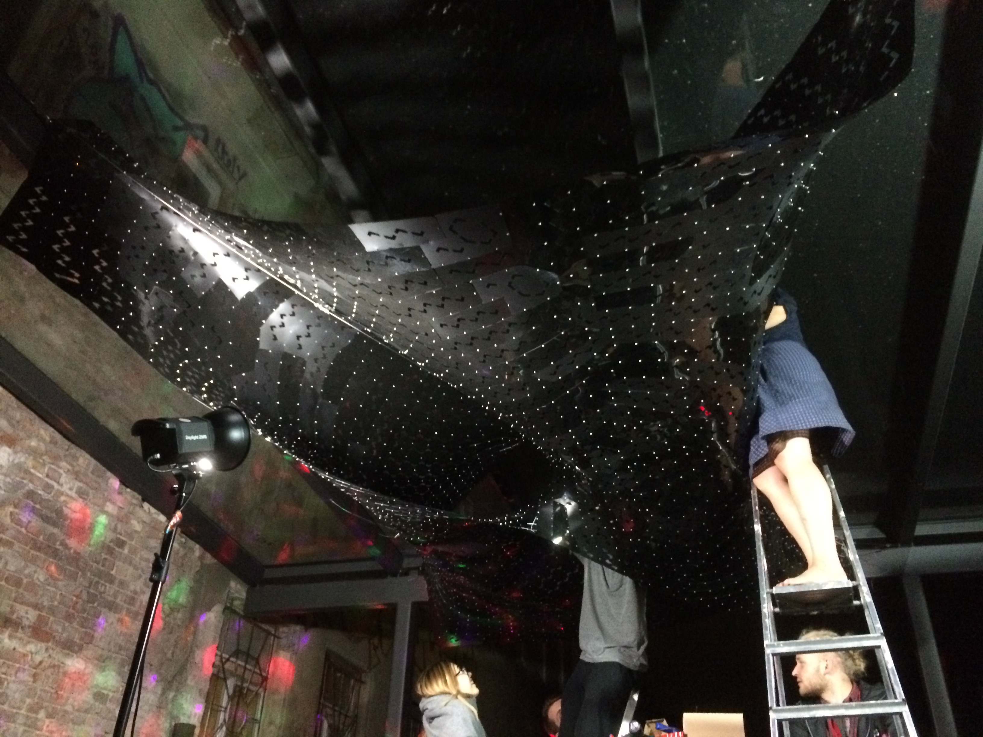
Assembly Fabrication was rolled out at the second weekend as a roller coaster of technical hurdles and challenges due to the workshop’s ambitious goal and was only mastered by an extremely devoted team of participants and our supportive host. It turned out, that we had to increase the subdivision resolution of our mesh geometry once more in order to meet fabrication requirements due to machine size and material availability. Fab Lab generously sponsored some extra material to realize the intervention in full size and made us spot unicorns with their never ending supply of sweet cookies after 16h of laser cutting at 4 am. It was no surprise that some workshop participants developed ingenious broom supporting techniques during the collective installation of the final assembly.

dsc09169_pshop

dsc09162_pshop

dsc09170_pshop

received_10210226689762605

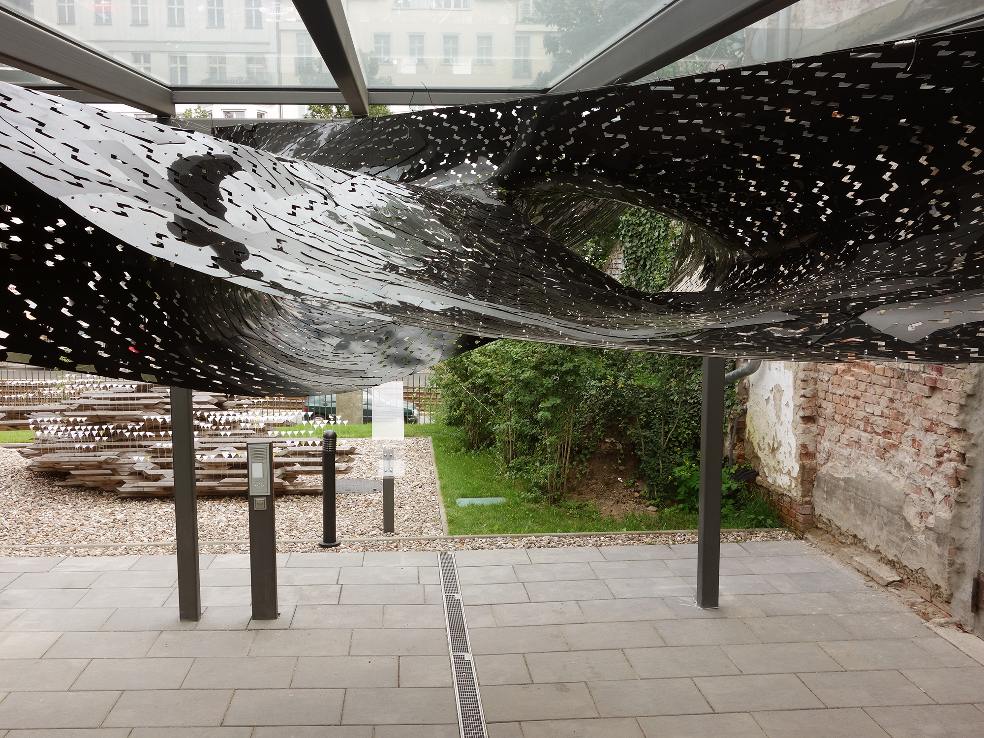
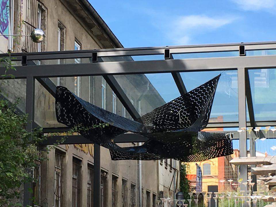
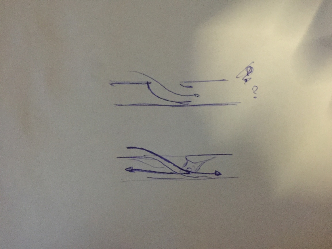
Reflections An important key insight an installation of this size, material, and weight (!) taught us, is that the occurring forces in an tension-active structure should not be underestimated and investigations in appropriate connection design have to be emphasized. The chosen material system turned out to have reached a limit in this scale and ideas are underway for the next generation of complex mesh installations.
Special thanks to: Daniel Hetzel, Natalie Peter and the Fab Lab for their courageous support and hospitality.

5 Likes

Thank you. Yes, I know where the image is from. Do you know more about the ‘low-poly input geometry?’
With millipede something similar can be done. But, I do not see how people in that workshop made those complexities.

try this
Credits: @AndersDeleuran

1 Like

I cannot understand how they made the hole. Do you might know?

problem soap bubble 04.gh (11.3 KB)

Hole was formed due to kangaroo mesh relaxation. I request @DanielPiker to help on this

1 Like