Hi guys, I need some help with my bridge analysis and its list structures. summary of the goal: I need to unroll flat a crv (axe of a bridge) that is bent in 3D, along with lines that are connected to it (stairs) and accompany its with data about its inclination, length etc…
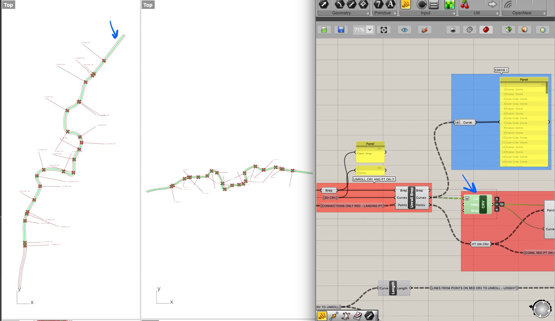
The definition gets already messed up in the part of unrolling (see blue Error 1) - gives me 120 lines, crv as an output of one input crv - with list item it was me trying to get away with it, it works but does not take the whole crv.
part and its error (see marked blue Error 2) is restoring the connection lines of the 3d bent crv (red bridge) in the flat, unrolled crv. Some connections are lost or represented on the wrong side of the unrolled crv (axis of the unrolled bridge), not sure where the problem is. I will be grateful for any advice.
Thank you very much in advance 220702_D2.gh (47.1 KB)
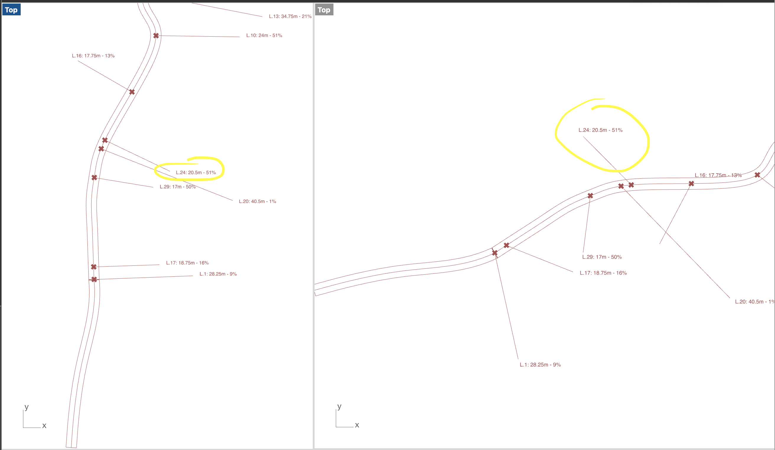
Hey, I have figured out some parts (all the lines are in the correct place and have the correct length ) still, 20 % of them are unrolled on the wrong side of the crv.
I think the first error is when the 3d crv unrolls - I can not understand why the unrolled crv is becoming 120 crv instead of one. My explanation is the bad brep so I have tried to create brep in many different ways, always with the same result;( I assume that this is messing with the direction of the line SDL afterward…
Do you have an idea how to deal with it?
Attached simplified definition and some screenshots
OK, ive fixed the many unrolled crv part. It was the foult of the brep. It sadly did not fix my problem tho. I think the line SDL will not work for what I want to do. Any idea how to unroll the crv together with attached lines so that they are displayed with its length on the right side of the crv after unrolling?
If you flatten the Points input, you now get 4 curves at the output of the Unroll Brep component (we will fix another issue later so you only get 1 curve at the output).
I rebuilt you input curve with a point count of 200 to maintain accuracy and used the output of the Sweep 2 component that you set up as the input to the Unroll Brep component. This produces one untrimmed surface, one curve, and 29 points at the output (this matches the inputs).
Hi Kevin,
thanks for stopping my monologue here with your constructive comments on this definition It’s impressive how neatly you solved it. Thanks!
There’s just one thing, I’d like to have them on the same side of the crv as in the 3D primary.
I partially managed it yesterday in a not-so-neat way - flowing the planes of the points on the crv and taking the same vector as in the primary version from that frame to the flowed point outside the crv. It worked, but of course, they now have now the same angle to the main crv as in the original, which is hard to read… I would like to have them tangent like in your example but on the right side of the main crv. Do you have any idea how I can do this?
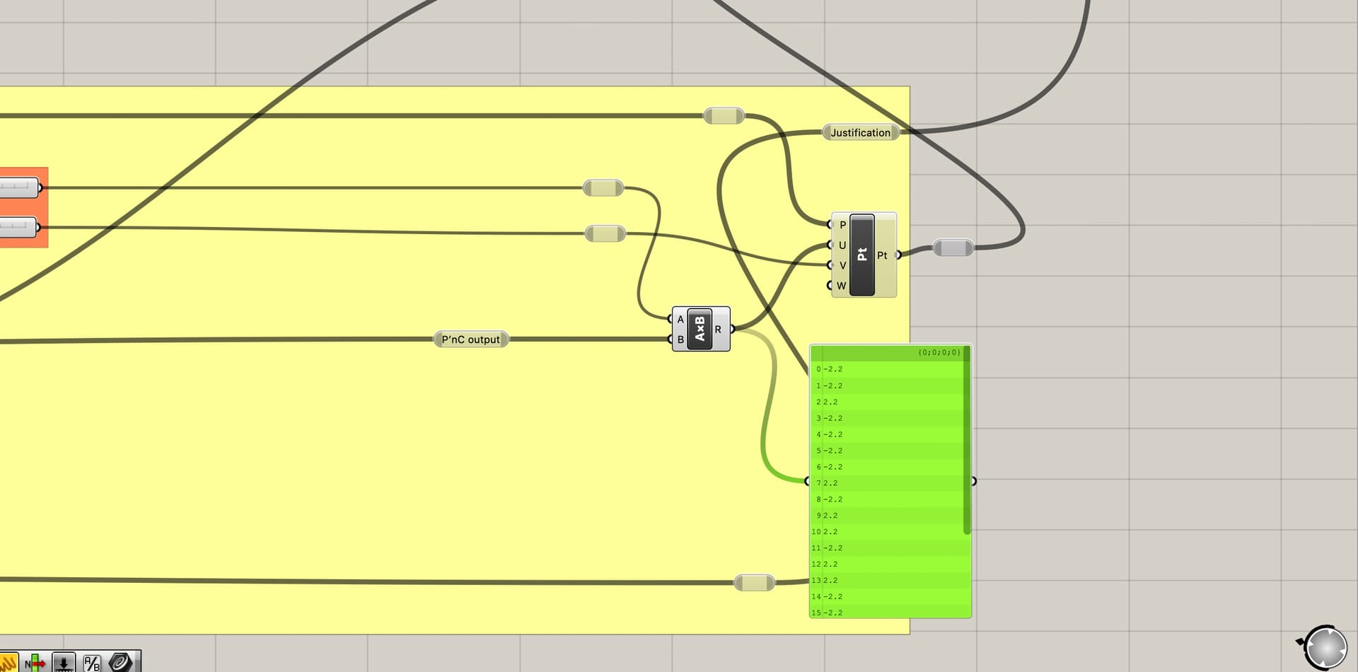
I don’t exactly understand what’s happening with the multiplication of the dotprod yet but it opens a new door def.
In the process of working on this, I noticed that when looking from a top view, the unrolled 3D curve was a mirror image of the original. I flipped the surface before unrolling to correct this.
Some of this is a bit messy, but it should give you some ideas to work with.
In your file, instead of (rise / run) x 100 you are using (rise / length) x 100
There is also a problem in the cluster where (i think) you are trying to calculate the absolute value of the rise. The output is the absolute values, but the list order is changed making downstream calculations erroneous (you are dividing the length of one line by the rise of a different line).
You can more easily calculate slope by passing the Theta (T) outupt of a To Polar component through a Tangent component then multiplying by 100. If you don’t want to display negative slope values, you can pass the output through the Absolute component.
Hey Kevin, thank you so much for the response and correction of the definition, super nice! I have learned so much from it. Filter, Bang, and Pick’n’choose save so much time! Also great idea with the bounding box to figure out on which side the crv should be!
I have two questions about the definition, if you could explain it would be great:
You used the main crv itself and the end pts (blue) of crv - connections (magenta) for defining the bounding box. Should I not first sort the start-end pt to have them alway on or outside the main crv ?
Hey Kevin, yes, i did figure it out too but solved it again in 1k steps (deconstruct the start, end pt and subtract z values)
I like your solution much more!
I wanted to use the 1, -1 output with a multiply component to determine if a vector was reversed or not (to differentiate between the 2 sides of the main curve).
To use as the Pattern input for the 2 Pick’n’Choose components downstream.
Yes, the output from the Filter component here could have been used since it already has the desired boolean pattern.
Here’s another version with a few changes (biggest change is combining the 2 groups for label placement). Also reorganized to eliminate a few components and improve layout.