I’m experimenting using Kangaroo to create a sort of radius around a flat panel because the shape is made up of straight lines and 2 curves and fillets don’t give me the result I want.
I’ve used Kangaroo to inflate the edges using Pressure and EdgeLength goals with a SolidPointCollide goal to stop the edges becoming overhanging.
It’s promising, but The areas around the pointy corners inflate less because there is more stiffness there…
Is it possible to pass a list of strengths to the EdgeLength goal that give less strength to edges depending on how close to these 2 corner points they are so that the corners bulge a bit more and are less pointy?
When you have a curved surface coming down to a sharp corner like this, it has to form a cone right at the corner, so the bending radius goes to zero, which physical materials don’t really like doing.
I do wonder as well if there might be a way to make this sort of shape with NURBS. It’s a tricky one, but maybe possible.
Thanks, that really helps.
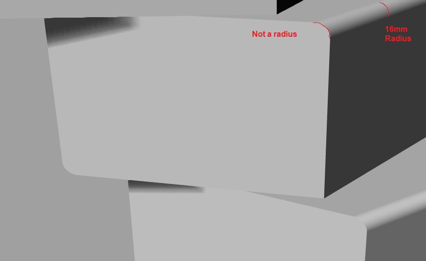
I have tried to do it with by tweening curves between the outer edge and offset but because the large rads in the corners are not actually radii everything seems to not quite work.
Just to clarify something on the Graph Mapper… the output is Y and is between 0-150. The input is X and is between 0-50. Why have you used 0-50 for the input? Am I right in saying this Graph Mapper takes low distances between corner points and edge mid-points and returns a low strength, gradually increasing, for any distance between 0 and 50. Anything over 50 units from the corner points will have strength of 150?
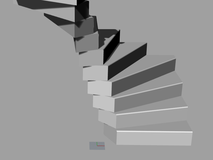
The end product is an end cap for staircase steps. Each step is a tapered plywood box with radiused edges that are cut at an angle…
I’ve tried but I don’t know how!
My Rhino skills are pretty basic because I always try and use Grasshopper
Attached is a rhino file of a step. I am trying to make an oak cap 23mm thick that fits on the smaller end and has a nice radius around its edge such that I don’t get an overhang to machine on the back of the cap and a tangential edge on the front of the cap…
You can blend two surface edges. I find this complicated. You need to add slashes for the corners. And I cheated by adding a small fillet on the sharp edges which will probably be rounded a tiny bit.
Just trying to recreate this so I understand it and to create a cap that is 22mm thick.
Appreciate that we are now talking about Rhino not GH but I am where I am!
It looks like part extending surfaces but then extruding the surface at the back of the step to avoid the overhang and keep it perpendicular to the stair cap (which is exactly what I need but I can’t figure out how you did this)
As I understand it, the workflow is this…
Extend / Extrude stair surfaces
Create plane surface at end of stair
Offset this by 22mm
Cut Extruded / Extended surface with offset and planar surface
Cut planar surface to fit end of stair (including cheat radius!)
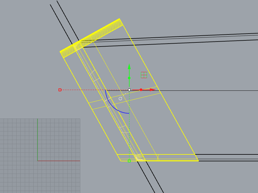
For the second last step I first created an offset curve. I deleted the corner two segments on the corners where the step has fillets. Then I filleted the four corners of the offset curve with a 2 mm radius. I turned this into a planar surface.
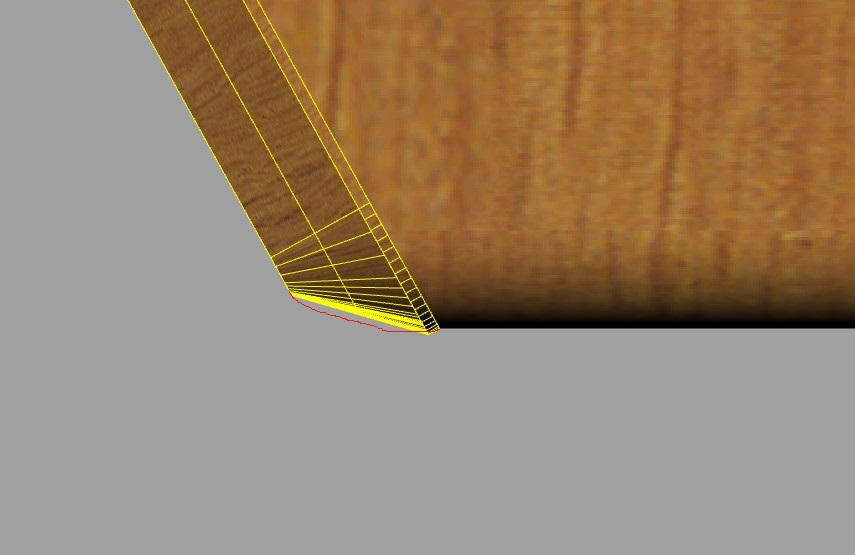
Circa mid edge on each straight edge I created a perpendicular plane and used these planes to create e section curve between the two edges.
I used the green surfaces and 4 blended curves for a Sweep2. I added two slashes on each corner. Note it’s not a blended surface, it’s a sweep.
I can’t get the end result, when I join the 2 planar surfaces and the sweep2, to be a closed polysurface and I can’t keep the cap tangent on the front end of the step despite selecting “Tangency” on that edge when I create the Sweep2… I noticed your example did not retain tangency either and it looks like its the corners bulging.