Hello, I’m a university student and am in a situation where I have to create the g.code to 3d print my own support structures.
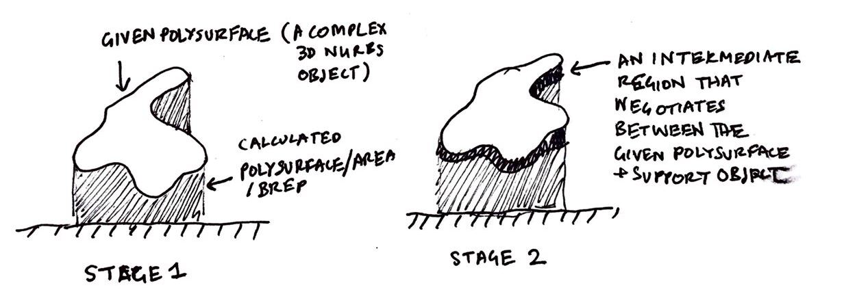
Basically, as the image shows, the first step is to generate a brep under the overhangs and undersides of objects. There have already been point based versions of this, for example here: Volume between two surfaces – Grasshopper where a series of points is projected. However, rather than just a rough series of points, I would like to create precise regions within which I can ‘trim’ my support structure (which will be another problem I’ll eventually have to deal with).
The second stage, if we can work out the first (i’ve tried searching for 3 hours and came up with nothing) is to further divide this region and create a buffer zone between the support and precise printed object (shown in the second part of the illustration).
JOSEPH THANK YOU SO MUCH!!! I can’t begin to expressive how appreciative I am of the time you took from your day to help a random stranger. Will just test this script out right now!!
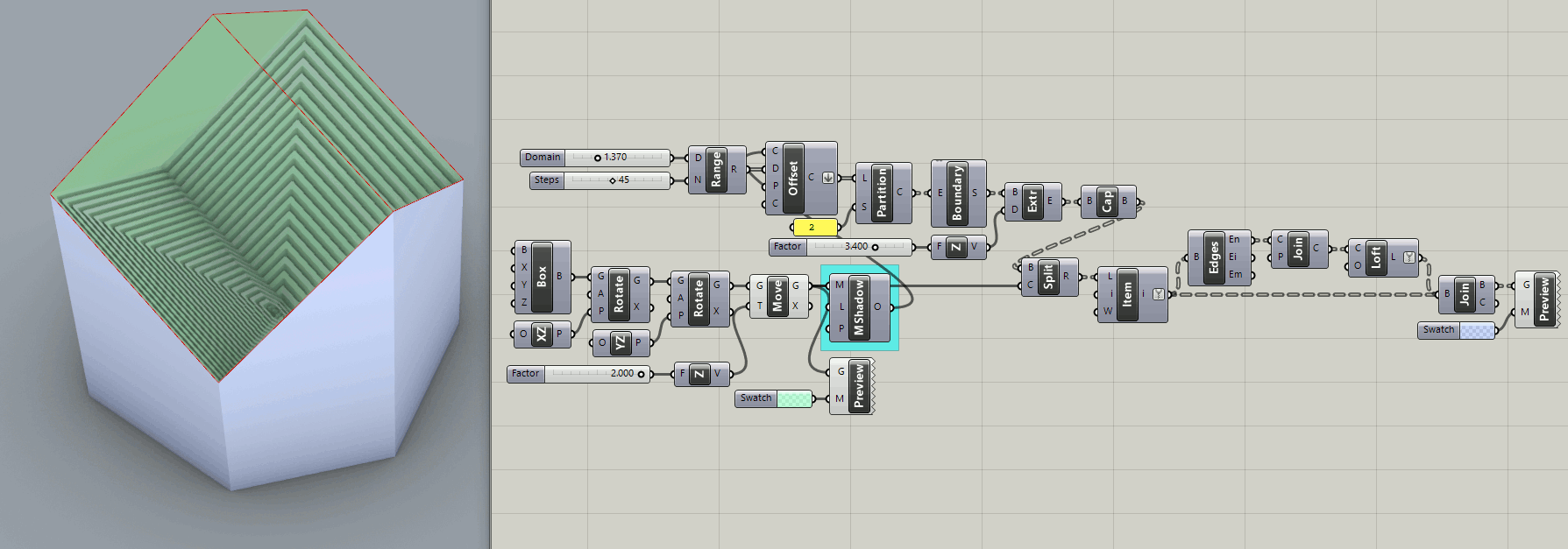
Well, don’t get too excited, it’s only an idle doodle showing how the base perimeter curve cast by MShadow might be used to create “support structures”. It is far from a definitive solution to the general problem of creating low density lattice supports for 3D printing.
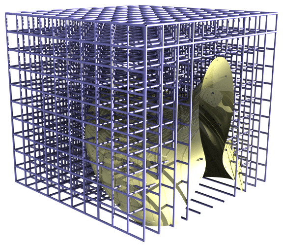
Now that I think about it, a lattice is similar to this scaffolding model structure I did three years ago on the old forum:
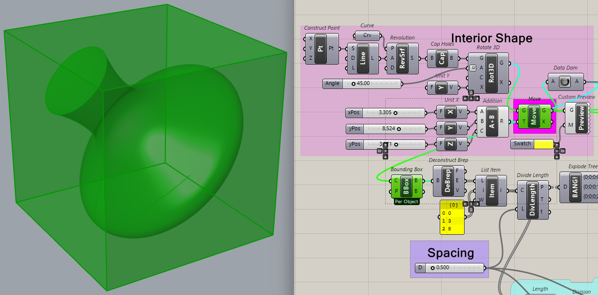
In both of these models, the geometry (vase) is created from scratch, then rotated and moved a bit. So in Scaffolding_2017Feb17e.gh, it would be the output of Move in the “dark pink” (fuchsia) group.
Mesh Looking… might work OK with a mesh, though the object you are replacing is not a mesh. Be sure to remember the slider values. If your mesh is substantially larger, small slider values could create too many scaffold “rays”.