Hull Fairing Methods

howdy, folks! I’ve been modeling a sailYacht since last week. I need professional assistance for hull fairing…

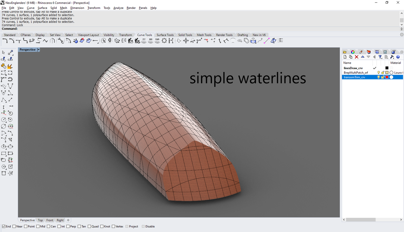
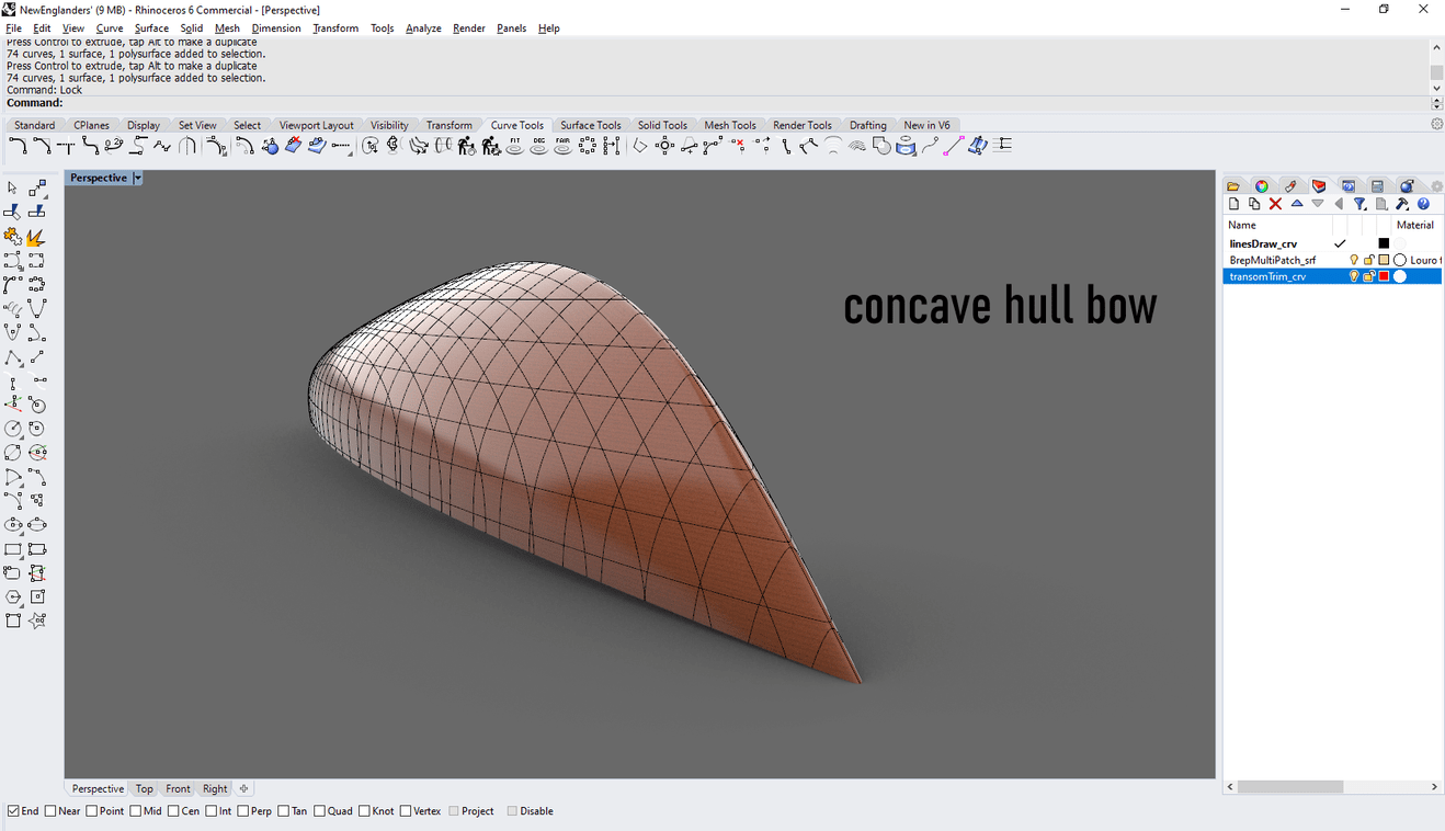
The surface of the hull is a Brep multiPatch. Each surface patch was originally built in third order, mathematically smoothest degree possible… but later on, it was increased to fourth order improve the tangency between srf patches for better looking zebras. the control net was doubled for better control over convex areas of the hull. partially below the waterline. is there anything i can do to fair these patches… some people suggest having the hull built in a single surface, but thats not recommended because in that process a lot of information and mathematical properties are lost… check out my hull please…

the curvature porcupine or curvature comb are said to be the best tool for surface fairing… i really dont trust crv porcupines because if you study the way they work, they only display good results for ‘‘arched’’ curves or quadratic curves since the radius remains constant. so, with that criteria we could state that the ‘‘perfect hull’’ should have spheric shape… what??? :smiling_imp:

cad softwares rebuild nurbs curves into ‘infinitely’’ small segmented arcs (depending on crvs complexity), tangent to each other, to display an approximate ‘’‘‘curvature analysis’’‘’ which is lit. how radius (r) of arc varies as a function of crv length, During this segmentation, the original nurbs curve losses significant mathematical properties… therefore we may state that curvature analysis does nott display very accurate results as we might think.

also, lets suppose you sketch a complex curve (DEG 5) and try to match it to a cubic crv. (we assume the following:

  • number of control points to be appropiate for accurate curve matching.
  • the weight associated to be rational (1),
  • almost ‘’‘‘0 deviation’’‘’’ from original cubic crv.

if you toggle on the crv porcupine, the results are going to be significantly different in each curve. thus, the shape may be almost identical (or have negligible deviation) but nonetheless the crv analysis is, and shall be always significantly different because the mathematical representation is different…

but then, you sketch another crv (almost identical curve) made up of segmentated arches… that quadratic curve (DEG 2 for circles, arches & ellipses) is going to be the smoothest possible representation of both DEG 5 & 3 nurbs crvs?

Rebuilding a deg 5 crv with a quadratic is not that easy, instead its easier to approximate the original DEG 5 crv using a cubic if increasing control point net… that should give the smaller dev among other choices mentioned above. since the order or degree is strongly associated with the distance between the Control point and the actual trace or path of the curve. (among others such as the weight input)


question… what curve is the smoothest?

Quadratic shows

  • areas on the curve where curvature remains constant or linear (porportional)
  • radiuses of arcs never coincide (discontinuities between curvature circle.)

Cubic shows

  • special distribution of curvature
  • continuity…

is there any tool out there for better representation of my surfaces? also, some say that increasing the order or degree of surfaces gives better looking crv comb… but in reality you are making your model’s mathematical representation stiffer and ‘’‘‘squarer’’‘’ i guess you could say…

What tools are commonly used by nav architects to generate accurate production lines???

Thanks again!

  • Oliver

is that special distribution of curvature not smooth? why?

Hi @oliver.jans

I use custom methods to generate hulls parametrically. I have different methods for different hull types and fabrications methods. Specific properties are controlled by parameters. By calculating the surfaces mathematically it is possible to use simple and clean NURBS topology which one cannot create or edit manually. Or well, it is possible to edit by hand but it is way too cumbersome, time consuming and the results are rarely perfect.

Do you mean your “comparison between quadratic vs. cubic”?
What I see is a curve with continuous changing curvature which has been rationalized with the _Convert command to arc segments. These arcs have constant curvature, therefore you see the steps in the curvature graph. Of course the original curve is smoother (if this was your question).

You do not have to worry about that kind of segmentation if it is introduced by the fabrication process for example for laser-cutting stringers or by milling a mold for fiberglas. Of course that’s a different story if you want to fabricate your hull from wooden planks or sheet material with certain properties.

How do you want to build that boat?

Hi @Jess! Thank you for your answer. That hull has been design for rendering but not for production… My intentions are to produce realistic model of a sailYacht to impress some shipbroker i met. Can u please name those softwares u use? Pricing? Thanks again @Jess

Hi Oliver,

That looks nice and smooth already. I assume it is a classic wooden hull? I’m not so sure about the stability for a sailing boat though. What kind of keel you have in mind? Any other specs? Can you post the hydrostatics? What are the skills you want to impress with?

Hi @Jess! This shipbroker is an old-school designer… not so familiar with CAD. He send me some yacht images, spirit 118ft, and said to model a similar yacht and with high level of detail. The hull must look professional. Its like a concept I’ll be introducing… this hull is primarily at the stage of prototyping. I can upload the hydrostatic table but I’ve been thinking in doing some CFD for better understanding and visualization… is there any free or low cost CFD to run? A naval architect suggested openFoam… but installation is complicated and the user interface is not so friendly… and youtube tutorial really suck.

The sailYacht above is a mixture of deep V and round bilge but no flare.

While not specifically a mathematical reply; the less control points the better the surface. I often rebuild curves when starting out to make them quite simple, not arce segments necessarily, but with minimal control points. This always helps in creating the most fair hull. One can not always minimize control points when created complex surfaces, but for the best of hulls, the least number of control points that does the job, the better.

Perhaps you should sign up for the online course the the Dutch Rhino guy is offering very soon. I can imagine you trying to use polylines and expect to get smooth fair surfs. Patches for hull are pretty sketchy too. Gerard has some free online short tutorials that can point you in the right direction.

Robb suggestions above are good too. He has a good background in the yacht modeling and that hull would be simple to do as a single hull surface mirrored across the x axis and then a bow cone fillet added for the soft entry at the stem.

PM me if you need help.

@Robb Hello There! as you’ve stated, it is better to begin with a reasonable amount of control points and to make them sort of ‘‘efficient’’ in a way that every point defines specific areas on the hull to distribute curvature in an homogeneous way… then a subdivision can be introduce to recalculate or reinforce the tangency between patches and to have control over some unexplored areas…

Thank you!

@jodyc111 Hello! Yes, I know Gerard Petersen. Professional course tutorials he offers. subDivision can happen for ever and deviation will always be negligible… you can maintain a very fair result but excess of control over some areas. the inverse process of subD unfortunately does not exist… having the hull rebuilt into a single surface is a difficult task… some CFD servicies demand that design aspect such as Van Oossanen’s from Heesen Yachts Computational hydrostatics. In my personal opinion the most accurate way of testing a hull is in the infamous tank test… van Oossanen performs at Wolfson Unit and then compares results from CFD and tank test. It is funny because in CFD, sea water has the same properties than nickelodeon slime. and results are very bad engineered. like our friend Gerard says: the proof of the pudding is in the eating.’’ the only way to test a hull, is making it run over real water. @jodyc111 you are very kind for offering help. I needed.

Hello Oliver -

I’m working on a series of tutorial videos that I will be posting to YouTube all about primary surfacing in Rhino. I typically do aerospace work but would love to do some examples around the marine industry, specifically high quality (Class-A) hull modelings. I’m wondering if you would be willing to share with me your input curves and your resultant surface, so that I could use it as a basis for showing how this could be approached in a more Class-A method. This will take me a bit, so it’s not like I’m offering immediate help on your project, but the issues you’re having are exactly the kind of things I want to tackle in my series. Let me know if you’d be open to that!

Best

-Sky

@sgreenawalt hello! you are very welcomed!

how would you like to receive the file? via email?

just in case, the hull above was deleted… :ive sculpted a better one. patches and lines are smoother. you’ll probable like it! let me show you:

whats the name of your youtube channel?

  • oliver

Email would be wonderful! I’m actually on V5, so if you could save it as a V5 file that would be great! My email is sky@schoolstreetdesign.com I just posted the intro video, you can see it here:

1 Like