TLDR: I would like to share my attempt to model “spiroid gearing” and ask for help to finish the generation script.
My goal is to get a geometrically correct model of spiroid gear pinion and hob and 3D print it later to test its performance. I am not a mechanical engineer, but I have studied several research papers and also a website calculator. My problem is that I would like to understand the theory behind, but resources are either limited or too complicated to understand.
This is why I came up with a “simple” model of the gearing.
I followed this research paper (1.6 MB) to get initial parameters, but then it’s just my attempt to continue with surfacing. As you can see, the model has many issues and a gearing like that won’t work in reality.
In the scipt below, I also calculated “critical surfaces” that obviously have to be cut off the hob volume in order to allow the pinion to spin without intersecting both volumes.
I would like to share my attempt for anyone to develop it further. I also would like to ask for help if someone knows the theory behind and can share it. My goal is to finish the calculator and share it with others.
You’ll have to decide how fancy you want to make the worm gear spiral shape and the toothed part it meshes with. I’d start with flat teeth just because they are simple to make. Curved teeth (I think they are called hypoid) are much more complex.
Spiroid is actually a registered trade mark and brand name for a family of skew gears designed for higher torque transmission than worm gears - the curved teeth are an integral feature of the Spiroid design. The patented Spiroid design was produced by Oliver Saari, working for ITW, in the mid-50s. The same company also produces Helicon gears.
Well gosh - that’s a new one for me - thanks for the info. I checked out the Spiroid website - their products sure are in a lot of different mechanisms. A friend of mine likes to design watch mechanisms and he is most interested in gearsets that have minimal friction. I think he uses involute gears because of this, and I wonder what the difference in gear-gear friction is between involutes and Spiroids.
I’ve printed a few different types of gearsets and roller bearings and it’s not clear to me that a standard FDM printer has enough resolution to print smooth running gears of any nature. Here’s hoping you can figure out how to do this.
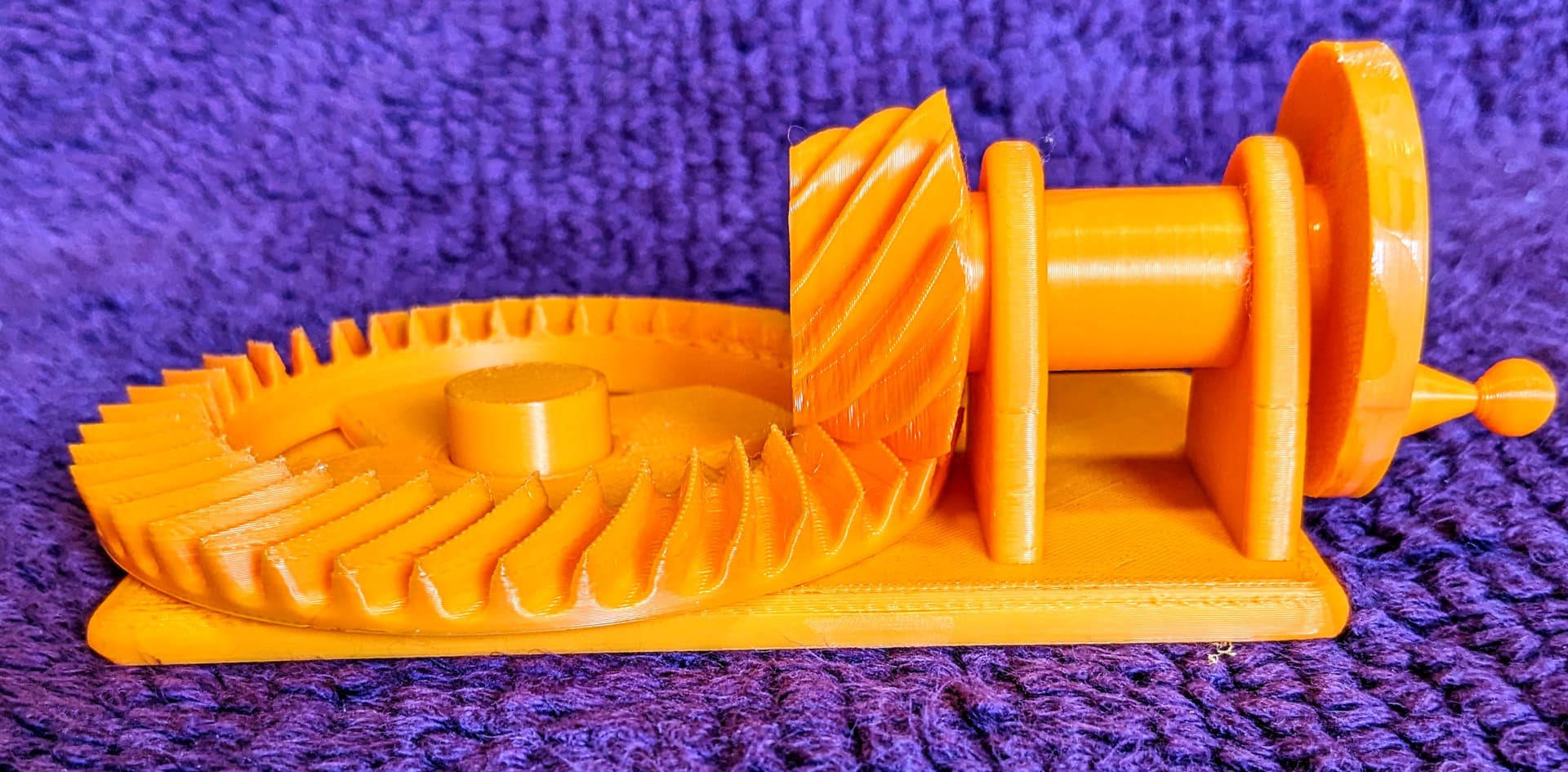
That’s an amazing example Seghier - thanks for posting it. I’m going to see about using it to make a 3D printable model that works via a small hand crank. Here’s what I’ve come up with so far:
Well done. I did my homework and looked into JavaScript of the website. There’s a part of the knowledge caldulated using AJAX and it’s not possible to get the source. But there’s also second part of the calculation which is computed locally using JavaScript. This part I used to write a Python script and Heteroptera’s “HttpRequest” component does the previous part. It’s definitely full of bugs and I haven’t tested this properly.
But still, I would like to know the theory behind this calculation in order to design a gearing more freely (e.g. set the transmission ratio).