Help with vase mode (3d printing)

Hi,

I am trying to replicate vase mode in Grasshopper but with a twist and I can’t get it working:

The Contour component produces planar “slices”, which are in this example called “base curves”. After rebuilding and moving some control points they are called “pattern curve”

My goal is to transform the “pattern curve” so it connects to the curve one layer above but doesn’t disrupt the pattern:

base curve:


pattern curve:

after transform:

I’ve been trying for days now and everytime I hit some wall. Does someone have an idea? many thanks for any help!


vaseMode.gh (80.6 KB)

1 Like

If i understand your result looks like helix?

vaseMode_2.gh (90.1 KB)

1 Like

thank you, that makes it more clear. Yes, exactly like helix - but the example I posted is very simplified. The shapes could be very irregular:

You can use the same script

vaseMode_2.gh (103.8 KB)

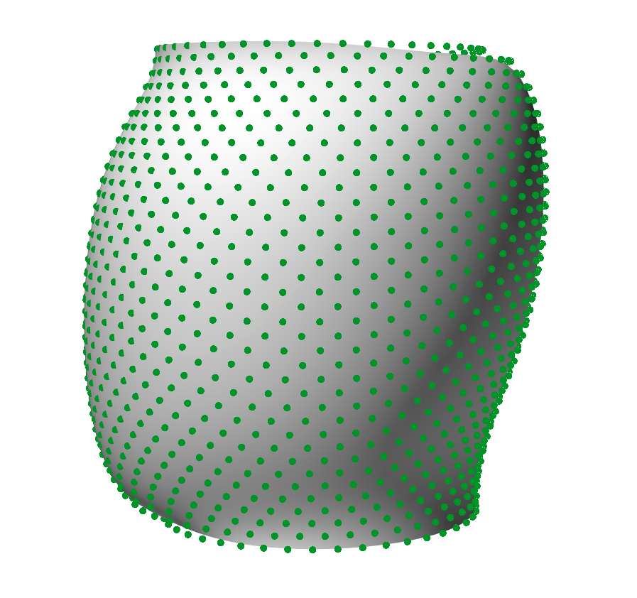
Thanks! Though the pattern is more complex than just normal “zig zag”, I am afaid: I takes the previous layer into account and optimizes the position of the “zigs” and “zags” to keep a nice grid:

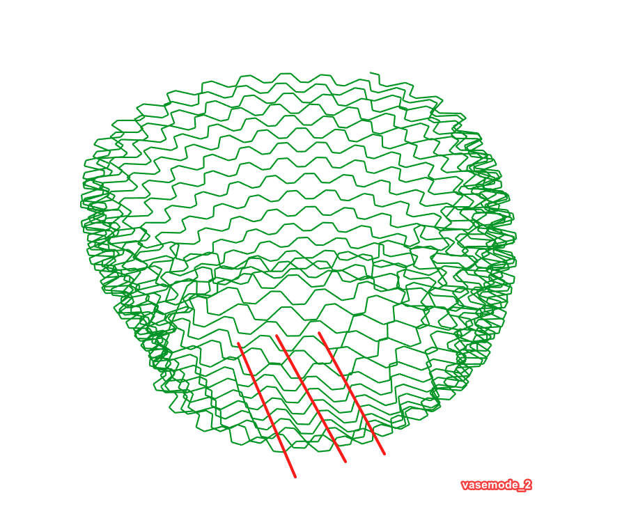
this I want to avoid:


edit: if someone is interested I can post the definition, I will anyway but when it actually works :slight_smile:

Are you trying to make a toolpath for the printer? Or do you want a surface of zero thickness you can run through a slicer program to create a toolpath?

actually I tried both but got frustrated with the slicer. You can import open meshes into cura as long as they can be sliced horizontally. Though cura does’t produce very good vase /spiral mode toolpaths, I am trying to make my own.

I know nothing about “vase mode” but it looks to me like one issue is that the seams are not aligned. I fixed that by moving the seam on all lines to the first point where they cross each other in top view.

The second issue is that alternate zig-zag curves are out of phase when spiraled. I wonder if it would work better to create a spiral from the circular “base curves” before implementing the zig-zag pattern?

1 Like

I think you are right that aligning the seams is necessary. Thanks

… and yeah, the “out of phase” problem is driving me insane. It gets kinda tricky when you look at more complicated shapes, and when there are not the same amount of points in each layer:

maybe one has to spiralize first and then do the dot distribution :thinking:
– or is this just shifting the same problem to the dot distribution part of the script?:thinking: :thinking:

Joseph: Here’s an explanation of Vase Mode:

  1. Make a cylinder 20 units high and 20 units radius:
    screenshot_01
    This cylinder has no thickness but it can still be 3D printed using Vase Mode. To do this you run the Rhino exported geometry (STL format) through a slicer program that produces the toolpath for the 3D printer.
  2. The slicer, in Vase Mode, produces this toolpath for the printer:

    A closer view shows that this toolpath is essentially a helix that is a single, continuous path from bottom to top; here is a section of the result that shows this better:

    Note that the path shown in the image will be printed from melted plastic that is extruded through a 0.4 mm diameter nozzle, so it is very thin and quite fragile. I would never print something like this because of this fragility.
    The concept behind vase mode is that it eliminates any surface imperfections caused by starting/stopping a print loop.
  3. For a “real” print it is necessary to give the printed geometry some 3D thickness. This is easy to do for a cylinder, but can get quite tricky for more complex shapes. Here is the cylinder with 1 unit thick walls:
    screenshot_05
  4. And here is the resulting toolpath that the slicer creates:

    Note that the cylinder is now comprised of many individual horizontal layers that are 3 loops thick. This is enough to give the print reasonable strength (although I typically make my prints a bit thicker.)
    More importantly, there is a seam (vertical in this example) where each individual loop starts and stops. These start/stop points create slight imperfection in the print’s outside surface. Dealing with these is an issue of it’s own.

Konrad: Maybe what you should do is create a single, continuous curve that has the shape you want, Pipe it, and print that.

Here’s what I got. Ignores your curves altogether and starts from scratch. Parameters adjusted to approximate your dimensions.


vaseMode_2020Sep18b.gh (97.4 KB)

Applying this idea to an arbitrary shape is a different can of worms! What shape?

as the feature size is of the pattern is very small this sadly wont work

thank you. the example I posted is very simplified and the curves could be very different than a straight cylinder. Have a look at post 3. and 5.

I saw them but there is no geometry posted. Image is useless.

The problem is that the dot pattern isn’t totaly regular but takes the last layer into account to optimize the distribution. Because of that dividing a spiral purely based on distance to the last point will result in “running” columns as seen here:


vaseMode_3.gh (266.8 KB)

I want the vase surface please, not cross sections.

vaseMode_3.gh (278.7 KB)
if you are wondering, yes the curves are offset inwards. This is because the nozzle will add some thickness

I ignored this part of your spec, at least for now… Sounds like a similar problem to laying bricks on conical surfaces?


vaseMode_2020Sep18c.gh (111.4 KB)

1 Like

Thanks!

Sounds like a similar problem to laying bricks on conical surfaces?

Yeah totally. It makes the helix part more difficult, since your zigs and zags are fixed on the surface.

In the simple shape like cylinder you can get this result but in irregular shape i don’t think you can.