GLSL Geometry Shader Text

Hey there,

I’m working on a terrain modelling plugin for Rhino. One crucial functionality is to have interactive contour display. It’s been a fun challenge to solve but I’ve got most of it figured out in GLSL.

Now, I’d like to create elevation labels for these contour lines. The actual intersections are computed in the geometry shader but I can’t figure out a way of accessing the point buffer generated in this shading step. Any ideas @stevebaer @kitjmv @jho ?

I’m working directly from a C# Rhino plugin and the attached GHGL file is only used for reference and ease of prototyping GLSL_contours.gh (462.6 KB)

A screenshot and short clip of it in action:

4 Likes

Well, I’ve figured it out.

Transform feedback will capture the outputs of a geometry shader. Then it’s a matter of filtering the resulting geometry and placing an elevation marker where we need it:

[EDIT] Here is another clip showing how labels can be dynamically adjusted:

6 Likes

That looks amazing. I’m assuming you must have done something beyond what GhGL currently provides

Thanks @stevebaer!

I forked the GHGL code, and adopted it to run directly from a Rhino C# plugin. For the above approach to work, I had to extend the existing GHGL functionality to include the following OpenGL calls:

glBufferSubdata
glBeginTransformFeedback and glEndTransformFeedback
glTransformFeedbackVaryings
glBindBufferBase
glGetBufferSubData

If you want, I can submit these as a PR to the GHGL repo.

Now I can use GHGL as a poor-man’s compute shader and pipe the results back to a buffer accessible to the CPU logic. At least until Rhino transitions to .NET 6 and we’ll be able to easily use proper hardware acceleration with https://www.ilgpu.net

A PR would be great. I’m usually a little slow to get them merged, but they are appreciated.

We’ll be on .NET 6 in Rhino 8 pretty soon.

2 Likes

Wow good work !!

Sorry, I was on vacation (but had no idea for your question).
Is this an internal development or your goal is to create a free/commercial plugin?
I’ve studied a lot of approaches to making land. My approaches are very different from yours.
And above all, I have strong constraints, altimetric elevations, flat or vertical surface, sharp edges, etc. such as: Terrain modeling algorithm
All of these solutions had the same problem, making geometric surfaces with organic surfaces.
Either the solution is perfect for organic surfaces or for geometric surfaces, but never both.
So I continue to model the terrain with a lot of objects and Trim or Boollean operations.
If your tool is not internal, how does it react to flat, vertical surfaces (see inverted, such as tunnel)?

jmv

Hello @stevebaer ,

Last year, only Rhino 8 for Mac was going to be on .NET 6 for sure.
Are you confirming today that Rhino 8 for Windows will be too?

jmv

That is what we are trying to do.

1 Like

good news !! :slight_smile:

@kitjmv,

yes the plan is to create a fully-featured terrain modelling plugin which will offer both precision and free-form modelling. I am a civil engineer/landscape architect and also find myself constantly switching between various packages to get the results I want. Mostly Civil3d for precision and Rhino/Blender for organic stuff. But I’ve worked with UE Landmass, Vectorworks and a few others as part of my research for this topic.

The sculpting part is more or less ready for alpha testing and I’ll post in on the forum soon.

The precision part is a hard one to crack, especially while trying to maintain interactivity with large terrains. My biggest pain is Rhino’s mesh structure - it becomes quite slow while poke-splitting faces, or splitting edges which are necessary operations to introduce new features to the terrain. My understanding is that each time a new vertex/edge is inserted into the mesh, the whole topology tree is updated. That’s probably fine for commands triggered from the command line but too slow for on-mouse-move interactive adjustments. Or am I missing something @stevebaer, @piac?

I had high hopes for @DanielPiker’s Plankton as a half-edge alternative but constantly translating between Plankton and Rhino’s mesh for display purposes is slow too.

Back to the original question, though. I’ve been thinking about truly vertical surfaces and overhangs a lot. It’s an industry standard that topography is depicted as a 2.5D mesh (one Z value per any given XY coordinate). One of the main reasons are constraints from the construction industry. Other than tunneling, all surfaces need to be dug out by a human, an excavator or a dozer. These operations are intrinsically 2.5D. Allowing for a fully 3D terrain mesh, while appealing at first, might be counterproductive and deceiving to the users. Especially when topography needs to be exchanged between other packages.

Having said that, my intention is to remove a lot of the overhead related to manually offsetting lines by 0.001 m to have close-to.vertical surfaces. IMO this should be taken care-of by the plugin automatically.

The plan is to gradually release feature updates and let users on the forum provide feedback and requests. I’ll make sure to keep you posted!

2 Likes

Arfff!! my work is omitted again :slight_smile:

To explain a possible use:

I make architectural models, it is useful for winning competitions or selling apartments…
Rhinoceros is THE software used in this domain (at least in france).
Today with lasers, 3d printers, CNCs, we can have very good precision.
Sometimes a 3D printer creates a reference surface on a model which is used by a CNC to place that model on the machine.
Sometimes a cavity inside the ground is used to embed a building with complex outlines (garage access slope, embedded terraces, etc.)
When I say to the software, “make a 90° angle that passes through this point”, It must make an angle of 90° which passes through this point, and not an approximation as close as possible.
Tolerances are to tenths of a millimeter.

That’s what I should be doing in my Delaunay implementation, but I can’t get into complex plugin development (that’s not my job).
However, I don’t work for NASA, so if a building in meters has a tolerance of 0.001m, I guess the unit could be in mm and a tolerance of 0.001mm is good for the architectural model.
(That may sound very precise, but machines also have their inaccuracies that accumulate. So ideally, my job is to have virtual models, …, ideal)

Hope you find this use case useful.
jmv

I understand the need for vertical surfaces for a CNC router. But wouldn’t it hit the same limitations with overhangs?

Could you maybe share an example project showcasing these requirements?

No, this is not our “traditional” manufacturing habit.
The CNCs are more like a 2.5D as you mentioned (for a 3 axis machine).

But 3D printing can do it since long time

Currently I make 40 or 80% of a building in 3d printing with extremely complex shapes as you can imagine.
But for the terrain it is not the same thing. If it’s not in our habits and if I don’t have many examples, it’s because there aren’t suitable tools.
Because of this lack it is faster to do the terrain by hand, as it was 20 years ago, rather than modeling it on software to send it to a machine tool.
We have technology that can do but not the tools that go with it.

but I had time to test
In my message on Delaunay’s algorithm, there are portions of this terrain:

Another project I tested in CNC with overhanging parts. We see badly on the photo, but at the top right there is a tunnel and another at the entrance to the bridge.
Obviously the terrain has been reworked to include these parts.

On these 2 projects many houses are inside a cavity.

jmv

So your ideal workflow would be to 3d print everything as one piece? Or would you still like the buildings to be separate elements, that just click into the terrain model like LEGo blocks?

We also build architectural models in the office and often like the flexibility of combining various techniques or replacing parts of a model if the design changes.

Also, looking at an underground structure:

Technically, the whole thing needs to be excavated first and filled later. I would still model these as two separate surfaces like so:
image

Or like this, if it makes more sense due to materials of choice, or just to better hide the seam:
image

Would that work for you? I am just trying to better understand the edge cases you might be running into.

Hello @mrhe

Do not look too much, If the vertical faces are important for me the inverted faces are very particular and rare.

Yes, even if it is a utopia.
there are many cases, like in your example, where cutting the model is easier.

The idea is that today, I have no choice, so the question does not arise.
But if a possibility is accessible, it is certain that I would use it.

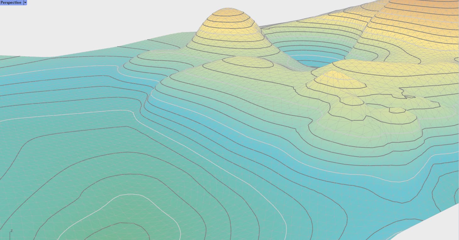
I found another example of organic/geometric terrain that I had wanted to achieve in 3d.
The idea of making the model in one piece is especially useful for the small scale white model (1/250, 1/500, 1/1000).

Here, the complete model can be produced by the machine, probably in SLA.
Finally it was easier to do it in PMMA and assemble all the parts.

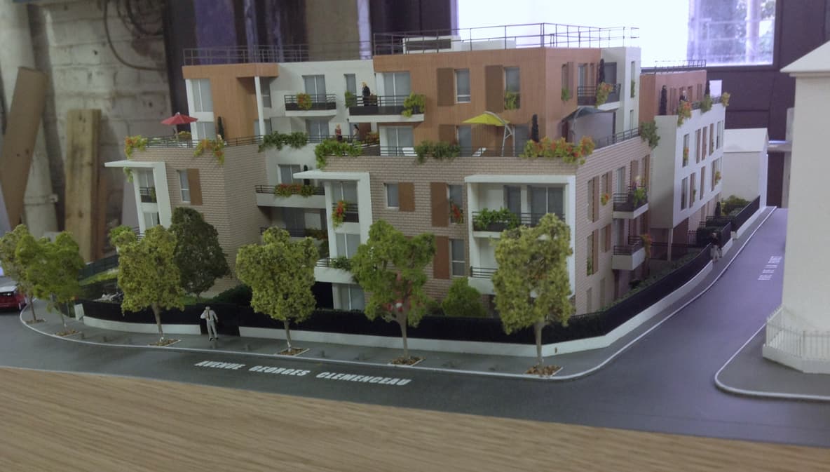
Here there is a small cavity but the floor was too small to add all the details. If I had the tools to do it, I would have done it.
Result, the buildings in SLA and the ground with a simple plate of PMMA laser engraved.

Here, if I could have made the gardens of the project in 3d, probably in SLS, it would have been really good. (it is possible of course, but it is not profitable)
The land seems simple but there have been a lot of adjustments with the building (half floor, catch-up slope, recessed terraces, handicap access, underground access).
All the buildings are in SLA and the terrain is in PMMA.

Here the CNC definition of the terrain of the previous aerial view. I don’t have any photos of the model. She was very big, 2m by 3m I think.
So machining on a 3-axis CNC in foam. Roads and gray surfaces are cavities where separate elements are inserted.

jmv

1 Like

Thanks for sharing @kitjmv!

I see what you mean with bridges and interchanges like in the first example. Probably it would still be a pain to remove the supporting lattice from a 3D print, but it could make sense for some applications.

The last example, where you show the digital model is very close to what I want to be achievable with the plugin. Correct slopes, stairs, ramps, retaining walls, terraces and building pads, linear features like paths, streets or streams and free forms like hills, dunes, ponds, or detention basins.

I’m also thinking of having a toggle, where all vertical surfaces would be truly vertical but users would be able to offset them automatically if they needed to for reasons stated in previous posts. This could be combined with a visual analysis mode, which would highlight the affected areas.

Thanks for providing some good feedback and food for thought!

1 Like

Indeed, you have just given me an idea for my plugin.
After creation the mesh, place All the faces of the mesh whose normals are almost horizontal, vertical.
this can also be a useful for you…
It remains to know which edge to move, and which edge to keep in its position.
In my way of editing the top edge is the most important.

Here you can see how you’ll be able to interactively grade terrain features and blend them with the existing ground. Users simply define a curve and tweak its position, elevation and corresponding cut&fill values.

Currently one needs to rely on vanilla Rhino curve editing tools to be more precise, but I’m working on adding custom controls which are better suited for terrain modelling such as slope or relative elevation difference.

This test is running on a 35.000 triangles mesh and consistently hits 80-100FPS. The plugin will feel very snappy even on large terrains.

4 Likes

Hello @mrhe

Sorry for what I’m about to say.
This is the classic method, very practical in the modeling of video games or when the architect is completely free in the space of his project.

In my case this method is never useful because I have to respect the plans. A slope is never defined by a curve and an angle (or an offset) but by two curves (like the loft function). A start curve and a finish curve.
Departure and arrival tangents are also important. Often slopes start gently (tangent) and stop with a sharp angle.

Consider this simple example:

Here the green curves are low walls, the slopes are almost vertical. where there is no low wall the slope is tangent.
The slope is never constant, just like the offset with the bed of the river.
In my experience, it’s always like that. Except in video games or when the project has a lot of space (highway, interchange).
If I model this example, it would be full of small surface created with the loft function.

I’m not saying it’s not useful. This method is usual, but the terrain created by my client is rarely (very rarely) so parametric.

jmv

Totally agree. In our work we’d also hardly ever use constant slope values along the entire length of a given feature. Sometimes it can come in handy for pond or detention basin design or embedding terrace-like surfaces.

The doodle shown in the above clip served as a playground to figure out the more complex aspect of interactively splitting the bigger terrain mesh and seamlessly blending proposed terrain into it. Next step is to do what you suggest and give users the ability to work with varying slopes. I’m thinking of adopting a similar approach to how Civil3d does it and have the top curve target another one (or multiple) at the bottom. As you said, in Rhino’s terms this would be equivalent to lofting.

Connecting 2 curves together is trivial. The more interesting challenge is how to aid the process of creating these curves. Especially the bottom edge is typically a result of some rules like min/max allowed slopes, space constraints or esthetical considerations.

You mention, that your clients provide you with detailed elevation values and you need to recreate them. I’m interested both in making your professional life easier and creating tools for the designers who need to come up with these elevations in the first place.

Please keep the feedback coming, I really appreciate it!

1 Like