In Rhino I’m trying to design a gear wheel of an old car that they don’t make anymore. As I’m a first time user however I’m running into a few hick-ups.
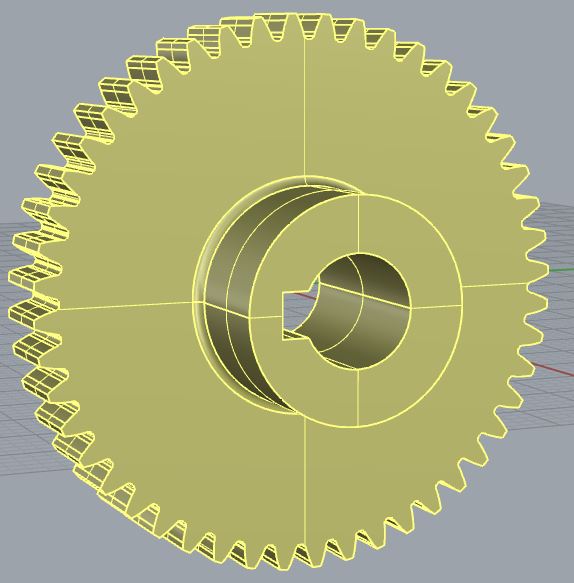
Thanks to an online CAD configurator, I believe the majority of the work is already done:
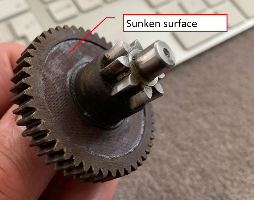
Create a ‘sunken surface (circular)’ in between the teeth ring and the extruded cylinder. Sink depth is 0.6mm. Bit difficult to describe, so following picture to clarify what I mean:
Similar thing needs to be done at the other side of the wheel (sink depth 2.4mm), but same trick should apply there.
I’ve tried adding circles or cylinders, grouping or joining them with the base model, extruding them, but I can’t get it to work in combination with the base model.
Then the other thing to do, is that the gear is actually helical, i.e. the leading edges of the teeth are not parallel to the axis of rotation, but are set at an angle of 8 degrees. Again, a picture to clarify:
The boolean worked well on both sides. The angled teeth I was able to fix otherwise. (knowing the depth of the wheel and the teeth angle, I worked out the rotation needed of one of the main front planes).
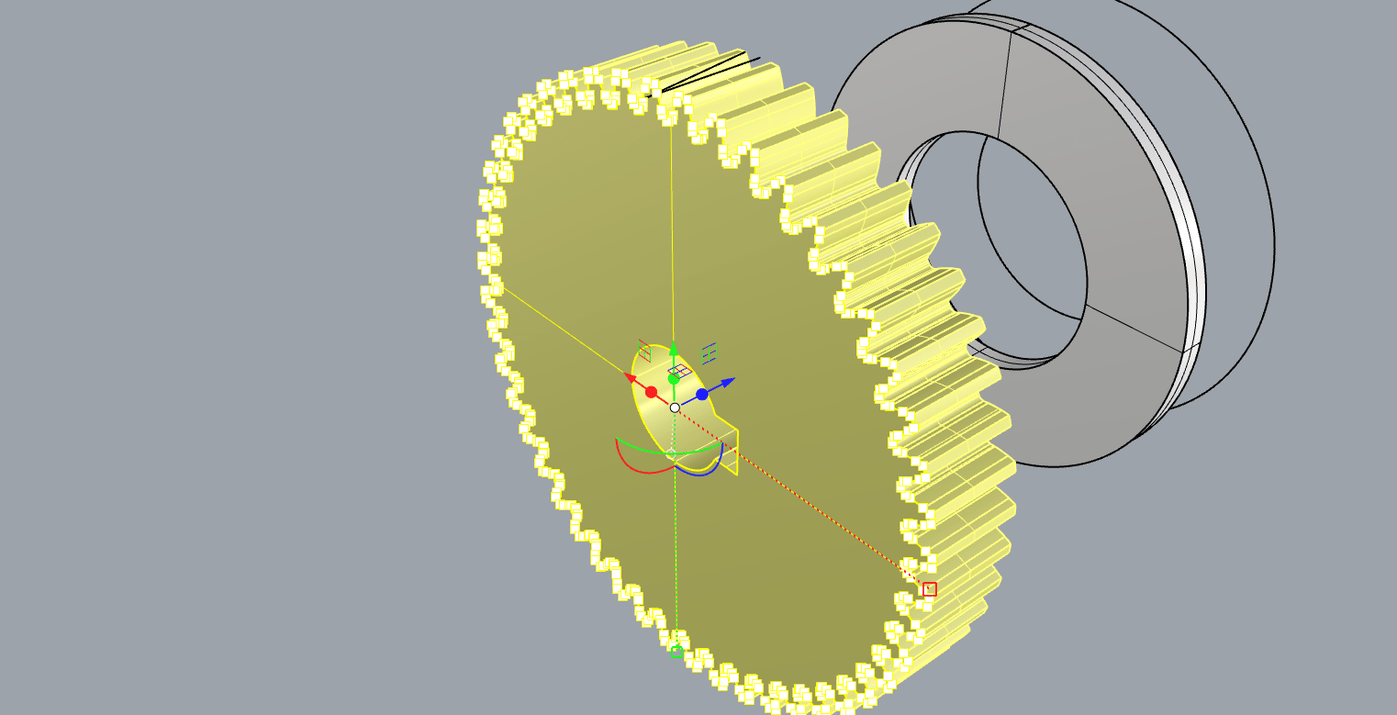
Only thing remaining is trimming/sinking of one of the shoulders, see picture for clarification:
Using boolean or trim function I ended up with sort of an open structure. Isn’t there just an easy ‘reverse extrude’ option? Or somewhere where I can set the depth of this tube?
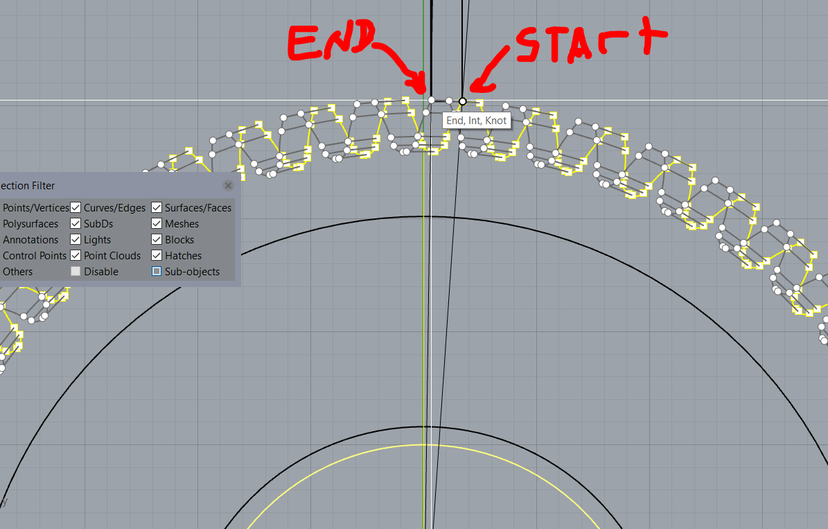
For this one, if I am understanding you correctly, you can “sub-object” select the face that is highlighted in your picture, then, with the Gumball turned on, click on the red arrow and type 1.4.
I noticed that you have a single surface on the other side that looks to be covering up an undercut in the shaft that probably isn’t supposed to be there.
When starting out with Rhino, it is good to learn that Boolean operations are simply automated routines to quickly intersect and trim pairs of surfaces. Ideally, you should have a firm grip of understanding how to perform these steps manually before jumping to the shortcuts.
The manual way of dealing with this undercut is to extract surfaces 1, 2, and 3. Delete 1 and 2. Use the single surface (the horizontal line in the following picture) to trim surface 3 and then join all surfaces.
Since the intersection between the single open surface and the gear wheel results in two closed curves, and since the normals of the the single open surface are pointing the “correct” way, the BooleanUnion result of these two also lead to the expected object.
-wim