I am using the fit plane component for multiples points, and I wanted to know what are the geometrical operations and/or the code which are run by this component.
As much as I like the way it works, it is kind of a black box to me. In particular in this example where the two definition in my GH script fit a plane according to the point around the node (notice that I only input the points labeled, not the center point). The pyramid example works just as one would expect, however I don’t understand why I get such a result for the ‘beam+column’ layout.
Does anyone have an idea how it works / how can we access the code so I could just read it ?
That’as a great ressource I did not know, it is exactly what I was looking fo in terms of code. However I did not found how it works in terms of geometric operations.
Hi.
Can I ask why you need that?
If you google “best fitting plane in point cloud” you’ll find many solutions; maybe it’s complex math, but probably not that different from what used by rhino engine.
Exposing part of the base code usually is not a good idea for a software house.
Again, why you need that?
(I hope to not bother McNell staff by replying before them, I’m almost asking out of curiosity… )
Other than that and if the plane is used for some other purposes [truss design and the likes] … in your example where there’s no plane (plane.Origin = node) that can define a half space that contains all the points (not the pyramid case, obviously) … you should pick a point, get a quideVector (point-node) and test the DotProduct (planeNormal, guideVector). Another way is to use points on the node edges at a steady distance from a given node and make an engulfing mesh (3 nested loops for that: find any triad that defines a plane that defines a half that contains all the rest points > if exists make a mesh from the 3 pts and append it to the engulfing mesh … blah, blah). Then use connectivity and control any suitable plane for your goals.
Hey there, thanks for these answers.
Forgive my English I am a French native.
@maje90 I am using this plane to join beams that lie along the axis and generate tenons along this plane. You may see what it leads to with this link https://www.instagram.com/p/BqQHP2-BR2f/ I already have a script that self generate the dovetails-tenons, and I use this great component. But as I said it is a black box to me, and I would like to understand what it does, even in simple words, in this case what’s happening at this point of my script,.
Which leads me to a second point, I am not so cumfortable with maths, never did a matrix in my life, which are what the google first answers deal with. I also saw that a plane can be described with an equation which is new to me, to me it was described by a normal vector or two vectors in space… Haha, I feel a bit ashamed here.
Finally, of course I understand how a sensitive topic it could be for McNeel to share the details of their programm, but what if they used a particular method, and they are others available.
From the link you provided, I’ll try a full reading but am affraid that I may sttrugle because of the lackings of my math background. Thanks for your help !
@AndersDeleuran Thank you for your link. Did not find anything about the fit plane command though.
@PeterFotiadis Thanks for your anwser. No I am not fluent in C#, however I have a few basics, And was hopping it would be enough to understand what happens if I would have an opportunity to see the code run by the component.
I kind of like the logic with your second idea, however I am not sure to follow you, what do you mean by ‘use connectivity and control any suitable plane’ ? (Maybe it is a mesh related vocabulary ? I mostly work with nurbs so I just miss the meaning of the word in this precise context ?)
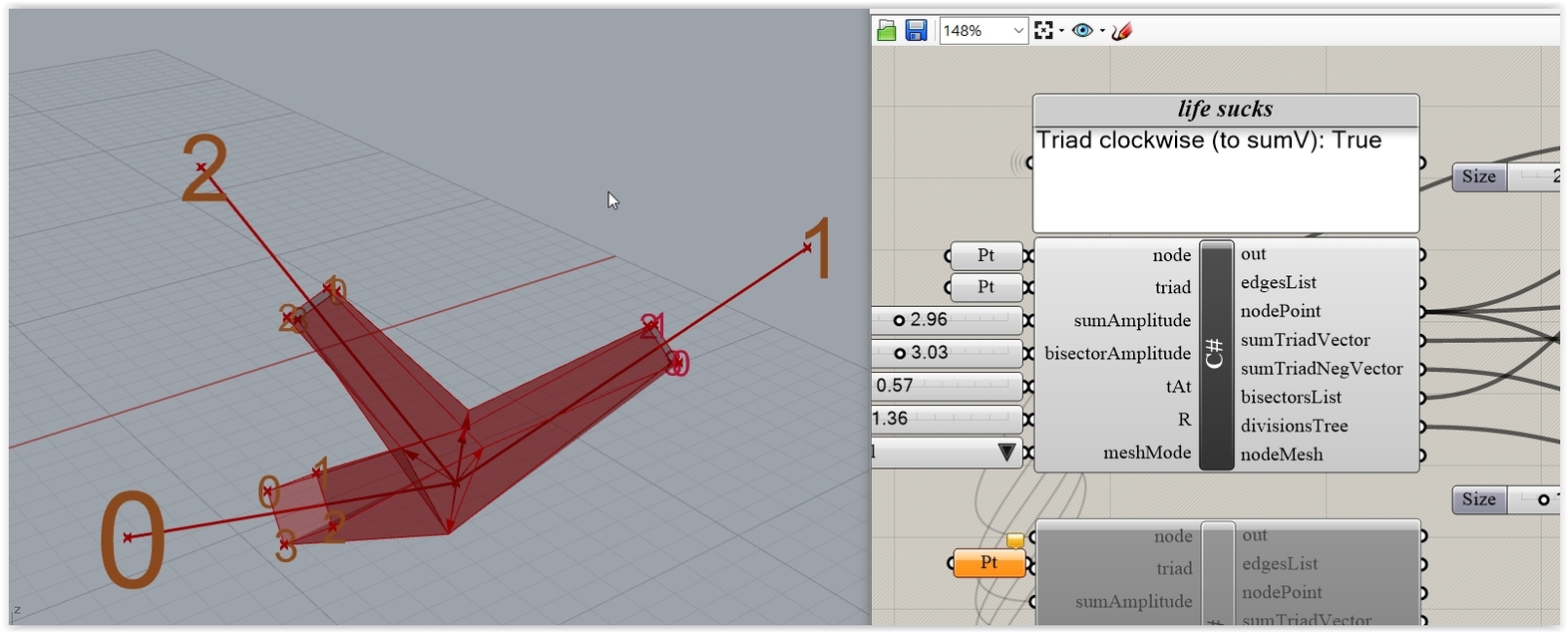
Well … your pics point me to classic irregular truss node puzzles where you must test for clash between members and/or design some bespoke (custom) node in case that you don’t want a typical MERO KK style of connection. This logic is used in stuff like Daniel’s latest (thicken a graph into a quad mesh). Here’s a small example: Imagine having a node with edges (>=3) and you want to create a kind of “connection” like this (shown half)
but taking into account all the “possible” triads that make sense (i.e. the vertices that belong to the faces of an engulfing mesh made via the logic explained above).
For just a single triad the “full” connection looks like
Having that kind of things in mind I said what I said.
Anyway by connectivity I mean that IF you can engulf the points on your edges (yielding a mesh OR a classic VV connectivity DataTree) then you can find what (3 pts) plane is prox to a given node, what plane divides the space in half (and maybe contains all the points, maybe not) and anything other imaginable. If on the other hand you just want to fit a plane to some points … then … well … all these are a bit off-topic.
To make a long story sort I could provide a “simple” (all things are relative) C# demo … but only if you are really after truss node design (otherwise the whole case/logic could be useless).
But … in order to understand the workflow (any workflow to be honest) you must be quite confortable with the basics (in this case: planes, vectors, dot/cross stuff, matrices etc etc). For instance for the what plane MAY define a half space … blah, blah puzzle mentioned you must understand what a DotProduct is etc etc etc.