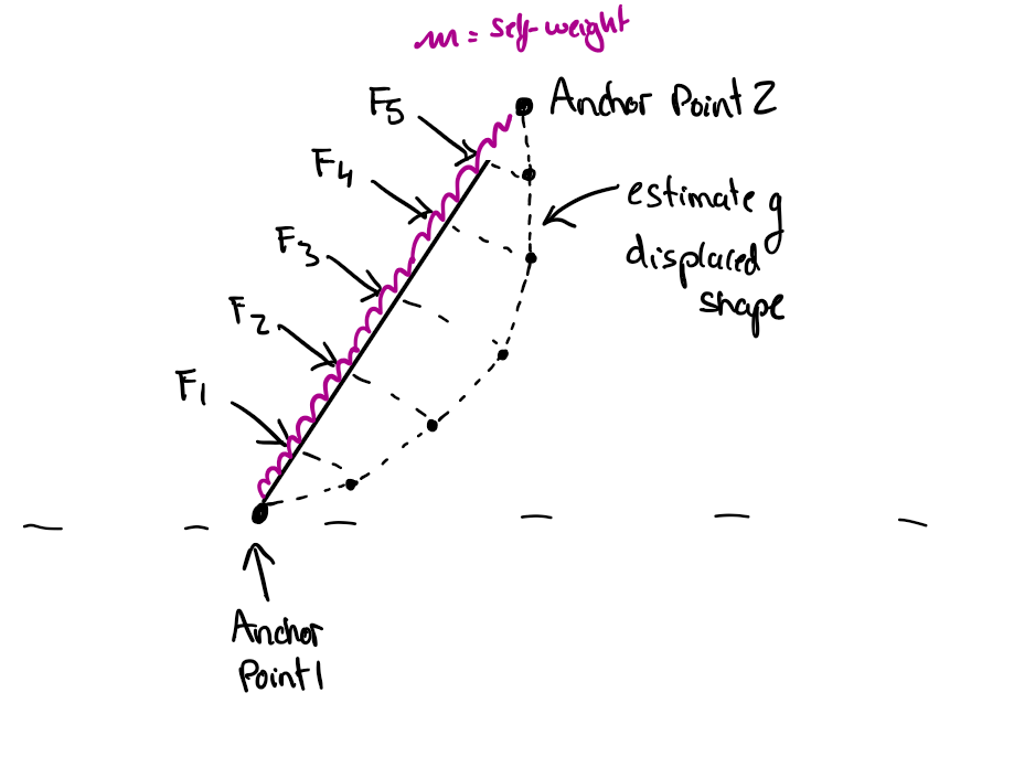
I am working on the design of a cable stayed bridge. I am in the early stages of defining the geometry of the piers. I intend to use a curve pier which will see load from its own self-weight and from five inclined point loads.
I want to maximise axial load in the pier and minimise bending/shear. To do this, I need to define the anti-funicular shape of the structure. In this shape, the structure will only experience axial load…perfect!
To define the anti-funicular shape, I first need to define the funicular shape. My understanding of the funicular shape is that this is the shape a hanging chain would adopt if the loads were applied in the orientation which would cause the chain to go into tension. Once I have the funicular shape, I can simply mirror the structure and change the direction of the loads, and this will give me my starting structure for the piers.
So onto the Grasshopper part…
I followed a nice tutorial from ThinkParametric (Kangaroo 101 - Physics Engine & Form Finding - Part 2 - YouTube) regarding how to develop a model of a chain under it’s own self-weight. This is working nicely and I can hang a chain under its self-weight from two different anchor points.
My question now is regarding the application of the point loads as below.
I am considering the following:
In the un-deformed state of the chain, I know the coordinates of the nodes which receive the point loads.
I know the inclination of the point loads as a vector (xyz) and the magnitude.
The nodes which receive the point loads must also experience self-weight force (just as all the other nodes do) in addition to the point load.
My current challenges:
Following the catenary chain tutorial I followed, the nodes are created by splitting the curve (which itself is defined by two points). I need to guarantee that the splitting of the curve results in nodes being placed at the coordinates I want to apply the point loads?
If the above doesn’t make sense, then I need to be able to add additional points ‘after’ the splitting of the curve i.e. I need to make additional splits of the curve at each of the point load nodes. However, I see that this can cause a problem because there will be different length segments in the chain.
I am new to Grasshopper but am finding it extremely rewarding. Defining the funicular form would be difficult without tools such as this. I have uploaded my .gh file. Any help will be greatly appreciated.
Indeed grasshopper and kangaroo are great tools.
Just, I hope you are using this for a preliminary study and not to actually build real bridges (properly engineered software and knowledge is needed…).
Totally not expert here, I just googled “cable stayed bridge”.
You refer to the “fan design”, right? Suspension bridge - Wikipedia
… uhm… the load is just vertical (gravity). Why/how you can specify the direction of the load?
Can you attach a picture (or whatever) of how the final bridge model should look like?
Note, kangaroo is good for finding equilibrium of opposing forces and general form finding, but it gets quickly tricky if you want a real-life simulation.
For example, springs with same “Strength” factor will deform (stretch/compress) by the same amount under the same load, whatever the initial/target length. This might not be totally intuitive.
(A 100mm spring with Strength=1 is made with a much “sturdier material” than a 10mm spring with Strength=1)
When you want to compare springs with gravity, you’ll probably end up with very very smaller loads compared to spring strengths…
@Callum_Wilson
I’m not following the description in terms of which part is the pier/deck/cables.
Could you include a sketch showing roughly the end result you are after?
I said it is not totally intuitive because one might think that “same strength” would mean “same material”, but actually it means “same deformation under the same load”. … too many words(?) sorry for the blabbering…
For example, to have a simple comparison between many rigid beams (same section and material, different lengths), to achieve correct deformations one might just use length^-1 as strength factor…
I see what you’re saying. When initial lengths are equal to the rest lengths, and the strength input is kept the same, yes this is true.
What is called the ‘Strength’ input actually refers to the k in Hooke’s law a.k.a. the spring constant.
One of the reasons I didn’t want to make the component do the division by length itself (which would have meant the user is providing EA instead of EA/L) is that it would have complicated the use of zero length springs, which are often useful in form-finding.
Zombie Kangaroo + Galapagos
Not fully automated, not really form finding with forces… but results should be as target.
I’ve interpreted main cable stays have to be parallel each-other… hope I got it right:
Thanks to both of you for your interest in this topic.
Indeed the Samuel Beckett Bridge is a good example. Although I don’t believe it is a true anti-funicular form (and so probably deals with quite a large amount of bending moment along the pier).
I have been completing some basic hand calculations of funicular polygons (which account for point loads but not self-weight) and they have demonstrated that in theory, some very surprising geometries can perform almost exclusively ‘axially’ e.g. the below which sees 5 x 1Mn point loads and is circa 30m in height. Exhibiting just 8kN.m bending moment is excellent for this example considering the magnitude and direction of the applied loads. Certainly a scary prospect as you say maje90.
The self-weight of the structure causes a major departure from axial behaviour…hence why I want to develop a more robust method for defining the funicular form.
I suppose in the above case the geometry doesn’t lend itself particularly well to transferring the self-weight to the lower support.
I agree though…typically the SW of the pier is negligible compared to the deck weight. Hopefully I can confirm this as a conclusion to this conceptual study.
Central pivot point “K”.
The sum of the momentum generated by the bridge cable stays is equal to the momentum generated by beach cable stay.
Each bridge cable stay have constant force and direction, but each cable have an increasing distance from the pivot point, thus momentum. Calculate total momentum.
Given a beach point, beach stay have a tension equal to the total momentum / beach stay distance from pivot.
Starting from the top going down, we can compute pier beams inclination by subtracting the bridge cable stays vector… one by one reaching zero.
Messy script, probably can be shrinked further …
Edit: oh, surely this doesn’t take into account the self-weight of the pier/beams/cables… i forgot about that!
bridge 3.gh (23.6 KB)
This version take into account pier node weight, you have to connect the 2 data dams and press the play button 4-5 times to stabilize it. (didn’t bothered using anemone…)
Pier node weights is constant, instead of depending on the shape or beam lengths…
Grasshopper won’t accept recursive data flow , so I did cheat it with 2 data dams, but that was just a lazy solution, certainly prone to create ambiguity like your questions…
I didn’t get chance to check the analysis in the other software yet. But this solution looks really neat! Thanks
I spotted that point 0 starts as {0,0,0} but at the end of the script point 0 is non-zero (suggesting it moves). I set the self-weight of the piers to zero and in this case point 0 remains at {0,0,0}. So it is the self-weight which moves point 0.
I’ve been trying to figure out how to prevent this happening…but without sucess