I want to explain my work for a moment: for my thesis I am working out how to build a pavilion with cardboard boxes. however, they are not cubic, but have the shape of pyramid trunks. The bases will be arranged towards the outside so as to be tangent plans to the surface given to me by the hypothetic customer. the entire system must have an important formal constraint: the faces of the pyramid trunks MUST, of course, be adjacent and belonging to the same plane, so that they can be connected together in reality with bolts or clamps.
In my definition I have a problem: these faces seem to have suffered a twist!
How can I solve the problem?
I have read the geometric definition of “flatness tolerance”: the tolerance value “t” specifies a three-dimensional zone limited by two parallel planes with a distance equal to the specified tolerance value. My idea was to build these two planes between the faces in which there is the twist, find the value of “t” and make the face stretch with the twist in the middle of that number. It’s probably a stupid thing!
For the question of overlapping faces, I was trying to isolate all the internal faces from the general list, as those belonging to the xy plane do not seem to have this torsion problem.
I ask one last question: I have isolated the normal vectors of the base vertices of the surface since these faces of the boxes must, of course, rest parallel to the ground. I did this by removing the z value from the vector components. How can I re-insert these new vectors in the same position as the general list of vectors normal to my surface?
I’m sorry for all these questions and thank you so much to anyone who can help me!
I don’t have the add-ons used in your def (I fact I have only Kangaroo) but by inspecting the pic posted in your other clone thread (BTW: Avoid - if possible - doing that) I suspect that you are after a solution called torsion free beams (That thing is what the name says).
If so you can’t solve that one without a Physics Engine (Kangaroo). See some demo cases with structures with non planar “beams” (i.e. beams with torsion: the more towards the red the more the torsion) and planar beams after Kangaroo does the job (green means a planar beam). I think that Daniel (the man who did the Kangaroo) provides a torsion demo in the K package(s) (but is VERY slow).
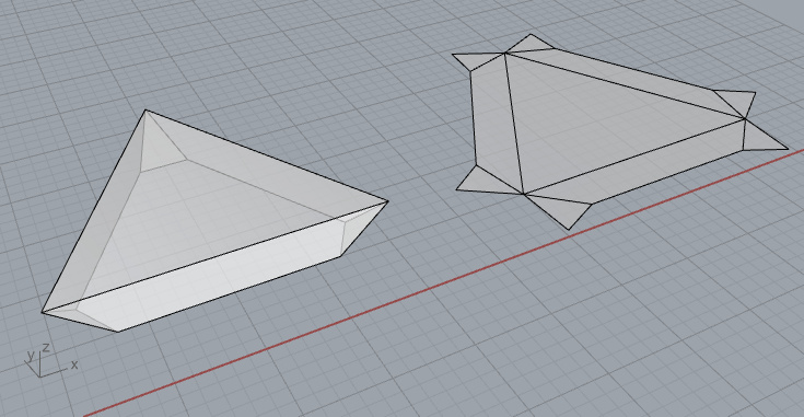
NOTE: The orthodox check for quad planarity is: the min diagonal distance should be less than a given tolerance. For instance (see the blue pieces below) if these structures are made from stand alone plywood/steel members then their deviation shown is a non issue thus they are 100% planar (in real-life). If on the other hand are made from glass … well … we need some milliseconds more to solve that one for deviations that are OK for glass (say 2-3 mm for a piece 0.60*2.4 m).
Thanks Peter, can you post here this exercise so I can study it step by step, please?
I’m sorry for the re-post , i’m new in forum and with grasshopper, kangaroo and all plug-in!
At this point I have a doubt: I created the “wings” of my boxes by sending the normal vectors to the starting surface from the vertices that define the bases of these boxes. Would there be an alternative way to produce the planar “wings”, without having the twist? Perhaps breaking down the vectors and changing (I don’t know with what value) its components?
Well … the thing captured above is pure C# code (meaning 100% useless to you unless you are quite fluent in coding) and is NOT an exercise: is a turn key real-life solution for doing these things in real-life.
The reason that I posted some indicative pics from what it does is to assure you that these things are doable in real-life … so you are not after a chimera.
Post here (WITHOUT any add on) a demo case in Rhino 5 format (a surface/mesh/anything) that you want to use as a template for your beams. That said the beam creation is easy - for feeding Kangaroo that is (but I’m gonna use C# code for that as well).
Warning: creating torsion free beams (in some blob type of topology) without a Physics Engine is 100000% impossible.
In the mean time get Kangaroo2 and spend whatever it takes to get FULLY the gist of that thing (you’ll need a month or two or maybe more).
I read again your posts. My problem isn’t like beams with torsion but is geometrically!
I’m wondering if there is another way to do geometrically (so it’s like solve the problem BEFORE) the wings without use physics plug-in (kangaroo) that of course can solve the problem AFTER. Read the post and my questions carefully plaese!
There is also a question about REPLACE ITEM IN A LIST.
You attempt to mix 2 different kind of animals: straight goals (like: I want this or that on all of my things) and dependent goals (llike: I want this or that on all of my things that are related each other).
As I stated rather clearly there’s absolutely no way to solve your beams with the ways that you know. Obviously I reject any beams that suffer from torsion (be from paper, concrete, wood or goat skin) BECAUSE this is a non rational approach and has NOTHING to do with any kind of reality (notably an AEC one). Excuses of type “I’m a student and I do this for fun” don’t apply because you learn/get used to do things the entirely wrong way. So your big issue is torsion free breams.
Either accept it and try to understand Kangaroo or try until the end of Time to solve a problem that is not solvable : kinda trying to divide by zero.
Even if you can do it for some geometries (like a sphere etc etc) you violate the rule N1 of Parametric design that dictates that you should being able to do anything using anything (within the limits of common sense).
Anyway if you want a 100% C# based solution on making beams (PRIOR Kangaroo) using any List that may contain either meshes or breps or both… notify.
Hi, I haven’t downloaded your definition yet, but maybe you can try figuring out why the surfaces twisted in the first place.
Meanwhile you can test whether they are planar with the “Is Planar” component.
I would first get the centroids of each surface, with Area or Evaluate surface.
Then I would test for planarity.
Then “dispatch” based on that condition. Dispatch both the surfaces and the points.
Then use “member index” on the points to get the index of the not planar faces.
Finally replace item. Your list is the original surfaces list. Your items are the ones from member index and the items to replace with are the corrected planar surfaces that you need to figure out how yo create.
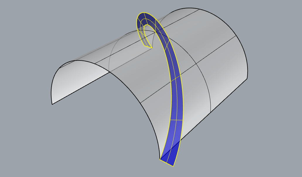
If you put a triangular grid of beams oriented so their planes are perpendicular to a roughly cylindrical surface like this, then you cannot avoid this twist you are seeing.
The problem lies with the diagonal members.
If you think about following one of these diagonals around the surface and extruding it out normal to the cylinder, you get something helical, like a screw thread:
To turn this into a beam and node structure, you can either make your beams twisting and non planar, or you can have a more complex node detail to accommodate the difference in planes where they meet, like these ones in Portcullis house:
This is easy to illustrate on a cylinder, but the same issue exists for almost all curved surfaces.
If your surface is fairly close to flat, one easy solution is to simply orient all the beams vertically, so the node axes are also vertical, but this becomes problematic if the surface wraps around closer to vertical at the sides.
To have flat beams and simple nodes where all the planes intersect in a single line like this…
…you are better off with a quad grid, since then the beams can follow the curvature directions of the surface and avoid twist in both the beams and the nodes.
Well …Daniel IF you operate in a country where the labor cost is reasonably low (China and the likes) I would suggest the self supporting modules approach (obvioulsy torsion free sides etc etc) be the modules quads or triangles. See the concept here on quads via laminated wood “beams” (side to side joints [metal reinforcements] not shown - kinda a linear “locked” hinge done with one single bended steel sheet member [custom angles per module, but that’s very easy and cheap to do]). That way you can simply bolt the modules together (via spacers et al) … while the node is just thin air.
sorry, in your first answer to my post your architecture is built with a TRIANGULAR grid (and not square like in your very last answer). Or better: you have added the diagonals to the square mesh, making it become the triangular grid. Since my structure is made from cardboard boxes, I find myself perfectly in this situation: the space occupied by each box follows the lines of the triangular grid, the thickness of the box must undergo (once the box is built) cuts 45 ^ in such a way as to
allow me to fold the cardboard
solve what happens in the junction nodes between the boxes.
Could you help me with the script?
I generated the grid with paneling tools, although I wanted to send you a definition without this plug-in (paneling tools) I couldn’t get to the point where I am without it. could you help me by installing this plug in please? @DanielPiker : Daniel, I think the key to solving my situation is precisely in the 45 degree cut / fold of my boxes!
@PeterFotiadis - That’s an interesting system - is it in use anywhere?
Also - have you tried the conical goal and face-face offset components in the recent release?
@mara.nunziante2 - Do you follow now why it is impossible to have both planar faces for your beams and make all the beams meeting at each node intersect in a single line when using triangles?
If these boxes also include a top or bottom face (I’m assuming you’re after something like this project: https://www.grasshopper3d.com/photo/albums/iass-expo-2015-pavililon-made-by-s-ren-jensen-consulting but with triangles), one possibility could be to simply cut the beams short before the node to avoid dealing with the clash there. You’d probably still need something to fix the angles of the beams relative to the surface though - perhaps some kind of corner like this:
Cardboard is very flimsy meaning that your only realistic solution is the thin-air node: i.e. create stand-alone triangular “modules” and then join them (spacers yield an airy result: a must) . Using wood would be way better mind. Avoid at any cost a variable node system that is 1M miles away from the scope of a primitive cardboard “demo” model.
After precisely cutting the 3 pieces (per module) arrange them in such a way where the foldable (long) sides lay in the outside. Keep them unfolded and fix the 2 opposite short sides (to the other 2: left/right) using a hidden cardboard reinforcement (a bended stripe, that is), then fold the open sides in place and glue the overlapping top sides. If you plan to join the modules via mini-bolts use pieces of balsa (very expensive) in the places where you expect the joining bolts to act (you can’t compress the cardboard box).
Now (having any template shape in mind [surface, brepface or mesh]) the fact that the triangles are planar (per bottom/top plane) doesn’t mean that their sides (your cardboard boxes) are torsion free. If you understand that … you’ll understand why I have provided all these pics (it doesn’t matter if the modules are quads or triangles).
Not sure how I can realisticly help you on that issue of yours since as I said I do stuff only via C# code (including Kangaroo solutions) … meaning that you wouldn’t be able to change an iota in a similar thing (nor to understand what’s happening and why). Plus I have no idea about plug-ins (in general) since I never rely on someone’s else work in order to bake my beans (Kangaroo excluded).
Note: 45 degrees cut is NOT a general rule - in fact is a 0.00001 minority case (having any shape in mind as you/we should: we are talking parametric stuff here [Rule N1: deal with anything]).
Note: since beams are in fact a 1:1 connection of vertices between 2 meshes (the OEM and another due to an offset) … clash issues MAY occur (rather impossible to deal with these without coding).
Note: for the connectivity part since the beams are related with topology edges a similar connectivity is used (vertex to edge, edge to edge and edge to vertex). Are you 100% familiar with mesh connectivity trees? Plus obviously you’ll need a layout policy (post Kangaroo) in order to have all your pieces flat in order to get the cut “patrons” for each box per stand alone module side.
See a static demo (A torsion free/planarity side status is a relative thing mind given the size of the modules and the spacers used) on that matter (2 layouts included: quad and triangular):
One of these days I mail you some pics from on-site work for the thing outlined above (modules are rather way more complex (and elegant) than the ones captured but the concept is the same).
Hope that you understand that posting the full thing (from any shape to min waste (packing) shapes for hydro/laser cut) is out of question for obvious reasons.
The only thing that I can post is making the abstract beams with torsion (prior Kangaroo).
Anyway this is more explicit with regard the folding sides per box per side per module.