Hi, just a quick question. How would I make parting lines out of the two arc like curves pictured? They are offset by .05cm which is the width and depth I want the parting line to be. Thanks

Hi Roman - do you want to create a small reveal there, a finished looking detail between two parts, or is this a mold part?
-Pascal
just like a small groove similar to that on say any product part line
Hi Roman - can you please post the surfaces?
-Pascal
are you looking for a file or a screenshot?
You could also make a circle from diameter at the start & end of your 2 lines. use the 2 highlighted lines to trim the top or bottom of the circles you just created, depending on the look you want. Then do a sweep 2 rails with the half circle arcs.
here is the surface. the arc goes in the x and y axis and im having trouble doing the extrusion.
final.3dm (2.0 MB)
Do you want the “groove” recess or extruded? Should it blend to nothing underneath?
You want it where you have the small surface. I have highlighted parts of it in my screenshot.

Hi,
I need it to be recessed, but I’m trying to get the whole curve where it wraps around the front end of the object too
Duplicate & join your edges that you want for your groove.
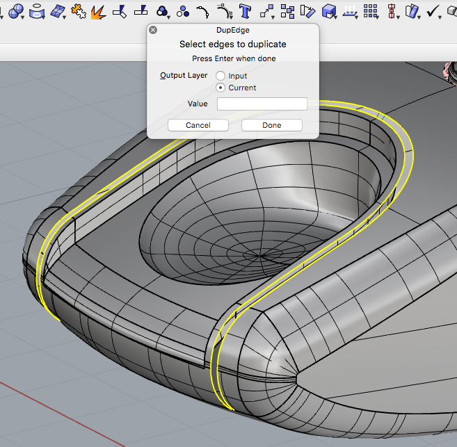
Do a circle diametre Vertical at the middle of the curves …


Trim the top of the circle and make sure that it is joined to your two edge curves.

Then sweep 2 rails from your half -circle to the surface edge at the bottom to flatten groove.

IHTH «Randy
final Rev1.3dm (2.2 MB)
1 Like
thank you. did you join them at the very bottom with a straight line?
I just used the edge of the polySurface when I ran the sweep. Sweep from half-circle to flat edge each half was done separate. I find it gives a cleaner look. I didn’t actually join the sweep, so you could see what i did.
For the underneath surface, I extracted it and then split with isocuves to get the edges for my curves.
I tried this and i ended up with a bad surface. not sure why.
If it’s for visuals rather than manufacturing (although you can use this method for both) it may be easier to draw the centreline of the split line and use the pipe command then use both objects to split one another.
Depending on how you want the split line to terminate you can add a round cap to both ends.
Andy
Hi Roman - a (slightly geeky, but nice looking) trick I like for this, if I need the detail to be modeled (otherwiseApplyShutlining- on Windows only for now, I think, sorry - may be good enough) is to cut the gap, how ever you decide to do that, and then BlendSrf carefully (Use ‘Add shapes’ sparingly if needed) across to fill in the gap. Then InsertKnot with Automatic in the U direction - this will result in a new, 7th row of control points on the blend, right along the center. Select one point in this middle row and run SelU to select the entire row. Now, MoveUVN the points inward a small amount to create the depression - the edges of the blend surface will remain smoothly continuous with the surrounding surfaces-

Reveal_PG.3dm (644.0 KB)
-Pascal
2 Likes
