Is there a method of isolating a portion of an object and bending it? I’ve a brass mounting bezel to model that in reality uses three tabs that are bent to secure the lens assembly. Would any recommend an effecient approach?
LensPlate.3dm.zip (404.5 KB)maybe use Sweep1 to built the one tab or extract the latches and use flow along cure using a curve which looks like your arrow. Then do the offset afterwards to get the thickness and array polar to duplicate them.
c.
Thanks Clement. I’ve another question. Have you any idea what causes this?
looks like a meshing problem. If this rim is a single surface, containing linear surfaces adjacent to circular or curved surfaces, use _Split with the _Isocurve option and _Shrink=Yes to seperate them from each other.
The command _DivideAlongCreases with option _SplitAtTangents=Yes does basically the same. If this does not work, please post the geometry.
c.
Explode the polysurface/solid. Use ShrinkTrimmedSrfToEdge on the two surfaces with mesh problems. Problems will be solved. Rejoin surfaces.
I got it. I extracted and then lofted replacement surfaces.
Thanks. I’ll look into ShrinkTrimmedSrfToEdge - is that the same as shrink trimmed surfaces? In that case I do use that often along with merge faces.
Another thread with a problem solved by ShrinkTrimmedSrfToEdge. Weird render mesh on simple shape
Both ShrinkTrimmedSrf and ShrinkTrimmedSrfToEdge shrink trimmed surfaces to isocurves and rebuild the control point structure. The difference in results appears to occur when trimmed edges are not aligned with isocurves. ShrinkTrimmedSrfToEdge will shrink until the new edge touches trimmed edges all the way around. ShrinkTrimmedSrf leaves a small margin. The “conventional wisdom” is that the small margin from ShrinkTrimmedSrfToEdge avoids problems which can occur when the surface edge touches a trimmed edge. But my experience is I’m more likely to have problems with the results of ShrinkTrimmedSrf than with ShrinkTrimSrfToEdge
The problems you see here can of course be fixed using various commands, but it may be better to understand where the source is and just rebuild the part with one single Extrusion. First of, the badly meshed surfaces are caused by some heavy reparameterisation values like: (1.52508e+14 <= U <= 1.52508e+14) how did you created them ?
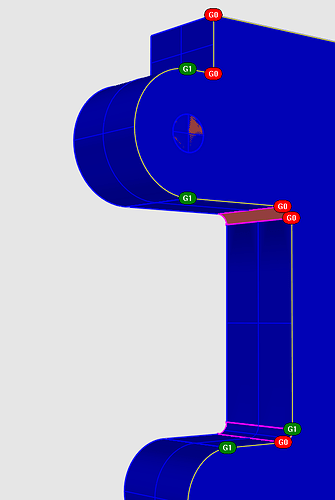
You might check out the originating curve highlighted in below pic, why are your fillets not G1 but sometimes G0 ?
Usually, if your curve is clean, you can just extrude it to a solid to built this part. To make sure that the linear surfaces are seperated from the circular surfaces, run _CreaseSplitting and set it to _SplitAlongCreases=Yes. I would sugeest you use this as your default setting and leave it that way.
c.
Well, the profile I used was checked and redrawn to have simple low point arcs. Everything was projected to the cplane for good measure and then the planar tool was used. Afterwards I moved the surface to where it needed to be and then extruded it.[quote=“clement, post:10, topic:31325”]
Usually, if your curve is clean, you can just extrude it to a solid to built this part
[/quote]
That’s my standard MO in these matters and I seldom run into problems.[quote=“clement, post:10, topic:31325”]
, why are your fillets not G1 but sometimes G0 ?
[/quote]
I really don’t know why such is happening. I’m using the fillet curves command for these corners. Perhaps I’m overlooking a setting. I did catch a discrepency after redrawing, joining and checking the points afterwards. A clean arc was changed to a multipoint version because one of the two curve ends being attached was not exactly verticle to the other.
The thing is, when I see clean control point counts, I’ve no suspicion the curves are not quite right.
I’m still haveing issues even after exploding, shrinking and rejoining. Even though all/every surface being joined has been shrunk.
WTF.3dm (225.7 KB)
Worked like a charm. But it’s not working on the last attached. Once the surfaces are joined again on the thinner piece, the mess returns. I use simplyfycrv as standard practice these days and look after simplicity at every point in the process. I don’t where I’m going off.
I just splitted by isocurve to do what i´ve written in my first reply and the object looks fine after joining it.
WTF2.3dm (335.7 KB)
c.
That is good, you might additionally use _GCon often to check your curve ends to each other, best to put it on a key like “G”…
c.
Which exact surface did you apply the split and where if you don’t mind.
Also, I notice there’s still a bit of wierdness.
That’s good advice. My impression at this point is modeling with rhino is almost as much inspection as it is construction.
In fact, If I were to create a course, it would involve a good deal of fixing otherwise sound looking objects.
That does not seem to be the experience of most users. My suggestion is to not just find problems and fix them, but rather determine what actions caused the problem.
Try try tracking the source of the problem. I´ve duplicated the border of one of the planar side surfaces and found it is closed, but not planar.
Curve_WTF2.3dm (219.5 KB)
EDIT: Forgot to put the fixed curve in, compare the two 0.5 fillets: Curve_Fixed.3dm (218.5 KB)
c.
Take this 0.5 fillet for example:

The single controlpoint is ok, but note it’s position. It should be located at the intersection of both tangents from the lines. If not, you might just delete it and create a new fillet.
btw. you might use _GCon as well to measure the angle between both lines involved into this fillet. I get a value of 89.986 instead of 90.
c.


