This Rhino command does not have a tolerance value one can enter like the normal Convert command does… In RhinoCommon, there is a tolerance that one can specify as an argument, so I wrote this script to test (you can try it on the attached file) :
#!/usr/bin/env python
# -*- coding: utf-8 -*
import rhinoscriptsyntax as rs
import scriptcontext as sc
import Rhino

tol=0.1
ktol=Rhino.RhinoMath.ToRadians(1.0)
crvID=rs.GetObject("Sel crv",4,True)
crv=sc.doc.Objects.Find(crvID).Geometry
bezz=Rhino.Geometry.BezierCurve.CreateCubicBeziers(crv,tol,ktol)
rs.EnableRedraw(False)
result=[sc.doc.Objects.AddCurve(bcrv.ToNurbsCurve()) for bcrv in bezz]
rs.SelectObjects(result)
sc.doc.Views.Redraw()
print "Created {} Bézier segments".format(len(result))
The thing is, I don’t get much variation (that is to say any) with tolerances (tol) larger than 0.1; and going down to .001 increases the number of spans by a bit - like 5% - but nowhere near what I would expect… So, any clue as to what’s happening here? I’m trying to find a way to nicely fit Béziers to a NURBS spline - even though I know it’s re-interpreted as NURBS afterwards… Probably barking up the wrong tree here, though.
Also, I guess there is a request in there for a tolerance option in the Rhino command… Assuming the algorithm is actually working as it should…
Hmm - I would not have expected this to have a tolerance at all, myself, so clearly I’m not the one to ask- I’d expect the Beziers to depend only on the spans in the input curve. Obviously, I need to talk to some bigger brains. Maybe the key is the ‘cubic’ part in your function - that is not part of the built in Rhino command, it keeps the degree of the input and splits it up per span.
-Pascal
To replace a NURBS curve with a list of Bezier curves, you shouldn’t use the CreateCubicBeziers method. Rather, you should use NurbsCurve.MakePiecewiseBezier and reinterpret the NURBS spans as Bezier curves. I can post code (C#/RhinoCommon) for this tomorrow - we use it frequently.
I see that, I can probably get that to work myself, bit I don’t think it’s what I want - I’m looking for a way to reinterpret a curve as a series of Béziers (for export to another software package) within a tolerance but preferably one that actually reduces the number of spans/control points and not increases them. Sort of a FitCrv with Bézier output. But I’m thinking that this doesn’t exist…
For conversion of NurbsCurve to Bezier curves, you could use the attached code (it is in C#, and depends on RhinoCommon).
Any rational NurbsCurve is first rebuilt with 10-fold the amount of control points, because I don’t know how to convert to rational Beziers. This has served us good so far but if you are planning on exact conversion of rational NURBS curves, it will need to support this.
A Bezier curve has an exact equivalent single span NURBS curve and vice-versa. So any multi-span NURBS curve can be converted into a series of Bezier curves. It appears to me that ConvertToBeziers does the straightforward conversion for both non-rational and rational NURBS curves to the equivalent non-rational or rational Bezier Curves. In fact Rhino considers the resulting “Bezier” curves to be single span NURBS curves.
For a simpler set of Bezier curves you could use FitCrv to generate a simpler NURBS within the desired tolerance of the original NURBS curve, and then use ConvertToBeziers to convert the simpler NURBS to a set of Bezier curves.
Rebuild - Look at deviation and adjust number of points in rebuilt curve as desired.
RebuildCrvNonNniform - Set MaxPointCount to the largest number of points which will be acceptable, then set DesiredTolerance to desired maximum deviation.
Hello, I have a question about the same topic. So I decided to ask right here. If I open an iges file, including multiple trimmed NURBS patches and use ConvertToBezier command, does it make the trimmed NURBS patches watertight as well? In other words, the multiple Bezier surfaces that I find in my output iges file after saving are gap free as in TSplines?
Cheers,
Hadi
Hi Hadi - I’m not sure what your question is - converting NURBS surfaces to Beziers will result in beziers that are water tight in the sense that you will be able to join them into a single polysurface where they are split apart but any trims on the original surface will be lost.
Hi Pascal, thank you for your answer. It was exactly what I wanted to know. To explain more, I want to use the Bezier surfaces in an isogeometric analysis solver that I have implemented. For this purpose, the surface must be gap free.
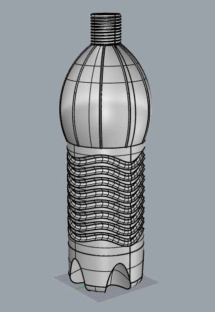
Hi Pascal, yesterday I tried to convert a moderately complex design of a bottle to Bezier surfaces using the command ConvertToBezier. The outcome is a bit strange. Some parts of the design (mainly the bottom part) seems distorted. Take a look at the attached Rhino screenshots of the original and Bezier converted files. The original iges file is also attached. Thank you in advance for any hint.
Cheers,
Hadi
Thanks wim, I am understanding a bit more now. So in order to avoid this issue, first I need to convert my trimmed NURBS surfaces to watertight TSplines, then I can use ConvertToBezier. Is that correct?
the problem is just that Rhino does not retrim for you. before using legacy software like T-splines you
a: retrim manually (come on its not much to do)
b: use another software,I know that Icem Surf and Catia does the retrimming for you, Alias does it as well I think)
c: extend you analysis software to deal with Nurbs
Furthermore I think T-Splines does not good things to your geometry, but I don’t know for sure
Edit: When converting in Icem Surf, the trimming boundary can still be a closed Nurbs-curve, depending on where the file was created. This is sometimes a problem in Icem Surf. So what I do, I save the file as IcemDB, open it in Catia, save it as Catpart and use the Catia-Icem Translator, which is good as hell. It converts all my Nurbs trimming boundary into Bezier trimming boundary.
So in case you plan to do this all day, buying a license of Catia might be worth the money.
I guess I prefer your option a. Option b is not really my type and option c requires the introduction of mechanical constrains between patch boundaries in the solver, which I don’t like. Could you please explain bit more on re-trimming such that I get a better idea before starting to implement that?
 but if you are planning on exact conversion of rational NURBS curves, it will need to support this.