I’m reaching out as we We need to manufacture a lot of large/tall anminal wire LED lights.
We need to build 600 of them, different animals, the logic is that we need around 10 cm spacing around them, and a little bit of human interaction, so they follow a little bit the anatomy flow…
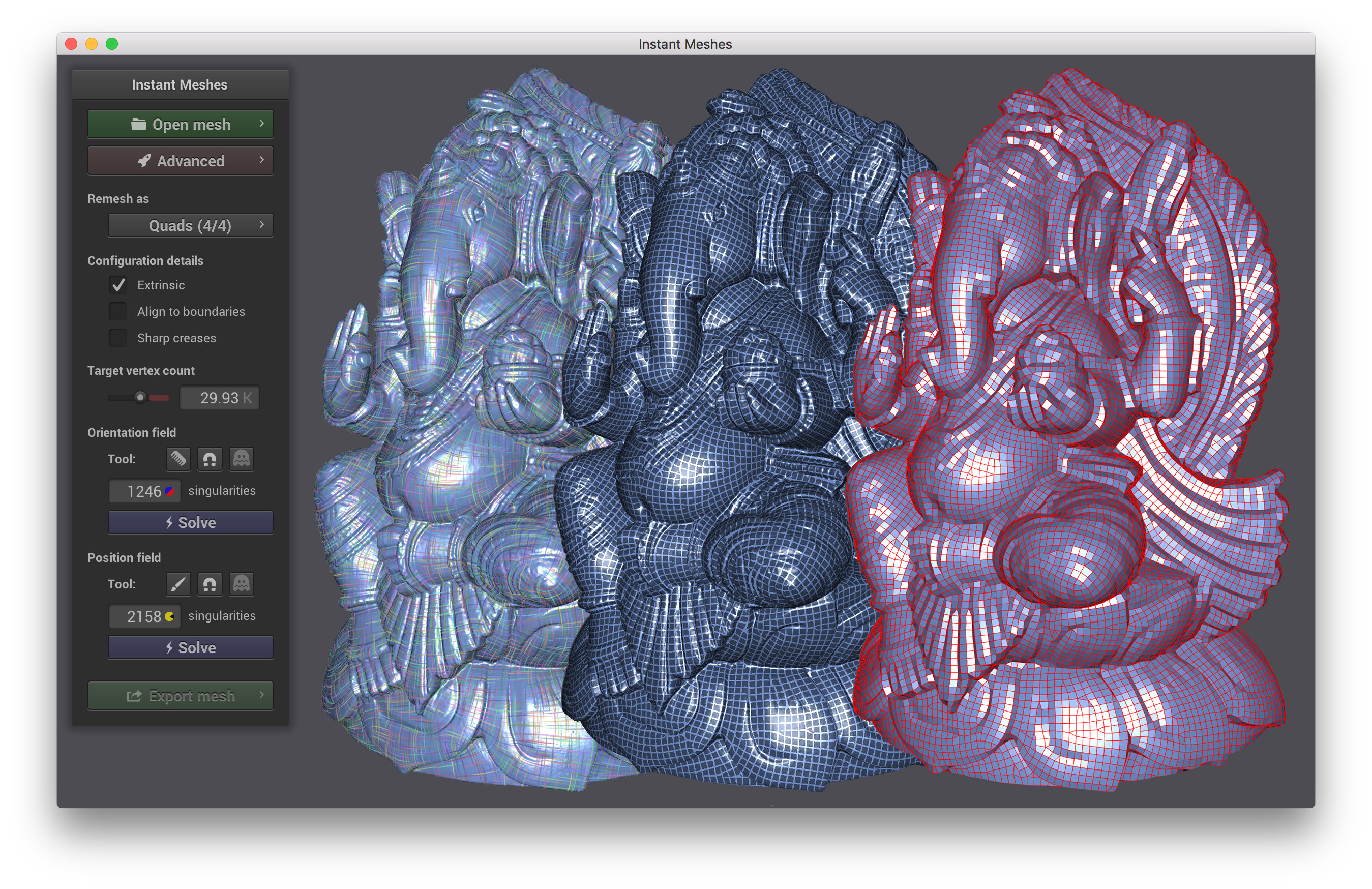
Piping (giving them thickness) is easy, what we need is a quick way to generate or help us generate the curves (with a little interaction for the flow), right now it’s all manual workflow, Zbrush mesh sculpt, snap curve one by one in Rhino then piping, Modo render.
Where the bottle neck is : " snap curve one by one" to the mesh, we need “at least i think” some sort or interactive shrink wrapping of crvs .
Is there any way GH could help in the process ?
Any thought will be so welcome ! Here is a final / example render Best Thomas
another ‘fun’ and worth-exploring method would be via the kangaroo plugin - you can do a variety of things like dragging curves around a mesh, or keeping points on a mesh and recording a trail, then turn into curves, or you can do a force-drive distribution
Thanks so much for all the help yes “does this mean your curves are different from the edge flow of the mesh (basically the same as question 1)?” Meaning as you know after a scan or even a retopology, the mesh point never have a nice edge flow… So if there was a way to shrink wrap things that will be great, if interactively we can slide with a background mesh constraint live…