I want to compare the differences in buckling behavior between modeling a lattice tower either as beams (3 rotational + 3 translational DoFs) or as trusses (3 translational DoFs): BeamTrussHinges.gh (84.6 KB).
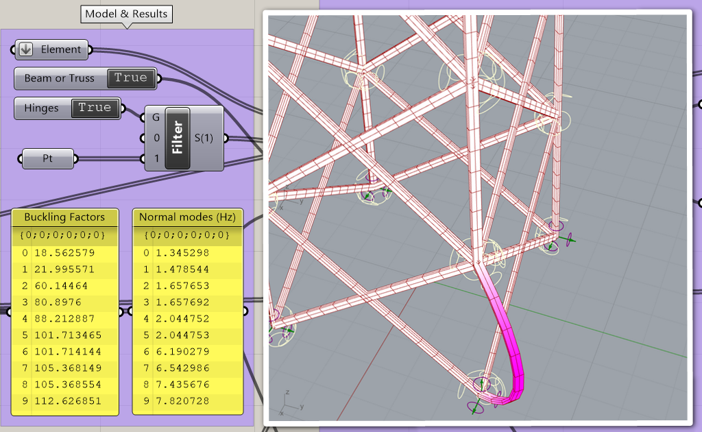
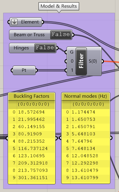
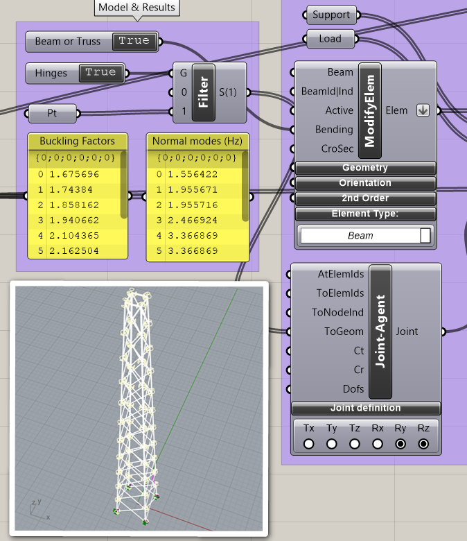
However, I obtain much lower buckling factors using beam elements (4.28) than using truss elements (13.93). Even lower buckling factors are obtained (1.68) in case hinges are introduced at each nodal position of the beams (Joint-Agent component). This is quite counter intuitive, isn´t it?
PS: The “Rx” radio-button in Joint-Agent must be unchecked, otherwise negative or close to zero modes are obtained…
PPS: Using Karamba3D 1.3.2 - build 200205 for RHINO 6
Maybe the ToGeom input is not the good way, try to use beam-joint-agent on all your diagonals to columns with an RY RZ relaxation, and with a beam-joint set a relaxation un RY, RZ on only a one ends of yours columns (To avoid having too much relaxation on a node).
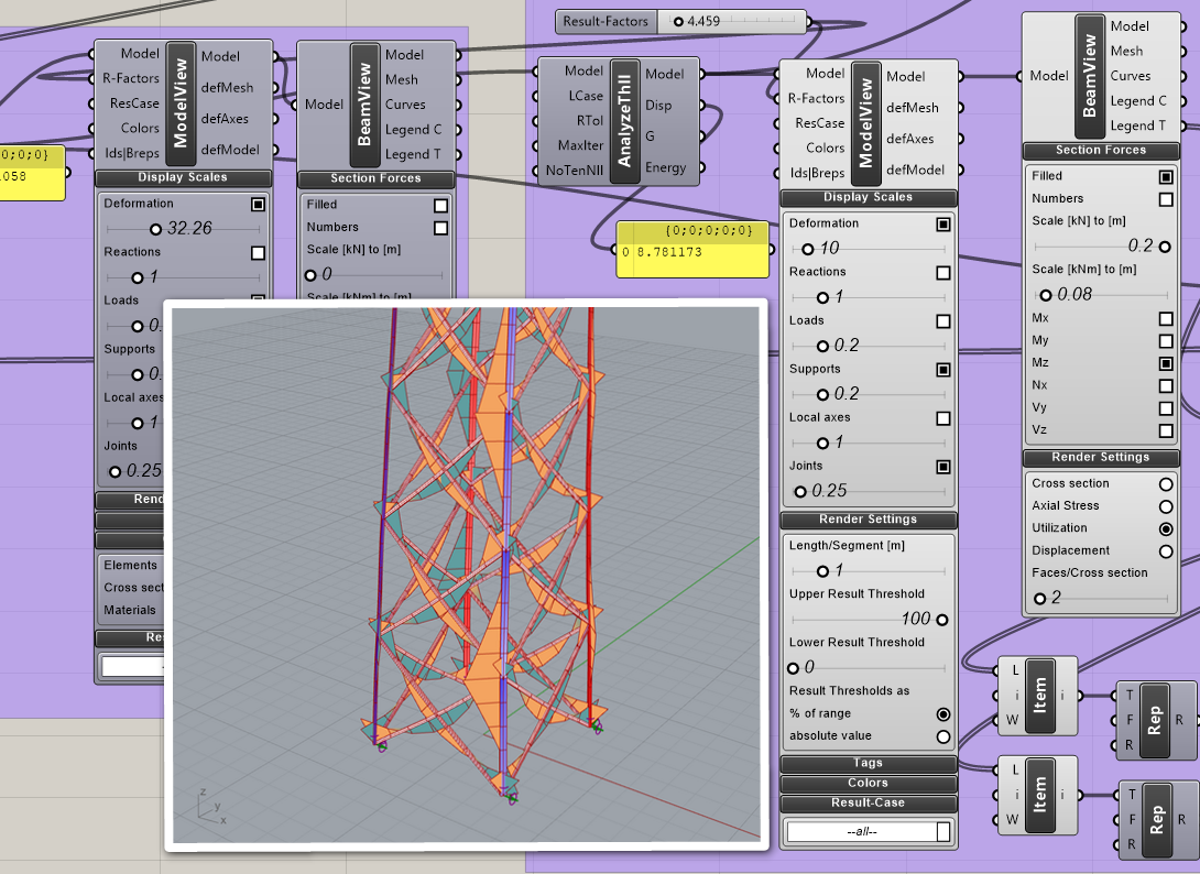
I agree with you, the relaxation is not being effective. My hinges are nor releasing momentum at all. In fact, the hinged beams structure develops more momentum in diagonal beams in comparison to the not-hinged beams structure. Note that the same scale is used in both images.
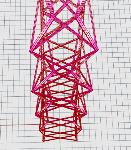
Look your deformation for each buckling mode,
On your first buckling, depend of your version,you have a global or local buckling mode
So you cannot compare your values if it’s not the same deformed first mode…
I am surprised that the columns are not continuous, especially with no conected diagonals each other when they cross.
You´re right, first buckling mode shape does not agree between the three different versions.
However, the buckling load should not be much higher (stronger structure) with Truss elements than with Beams, no matter the buckling modes shape is. Don´t you agree?
Similarly, it is also unfeasible that the “hinged” version locally buckles since we have just seen that the hinges are not releasing moment transfer…
This is all weird… I can´t understand it, sorry.
PS: The diagonals are intentionally not connected each other when they cross. Columns must be discontinuous to join the diagonals (I don´t know if I understood you well here).
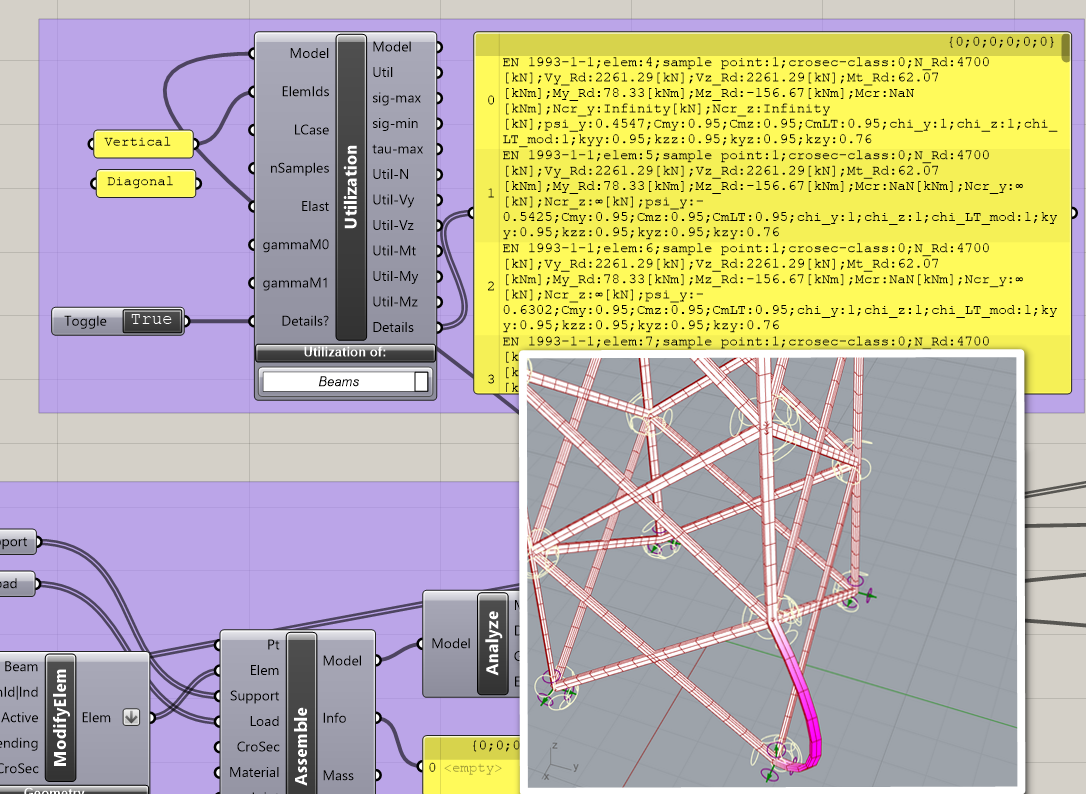
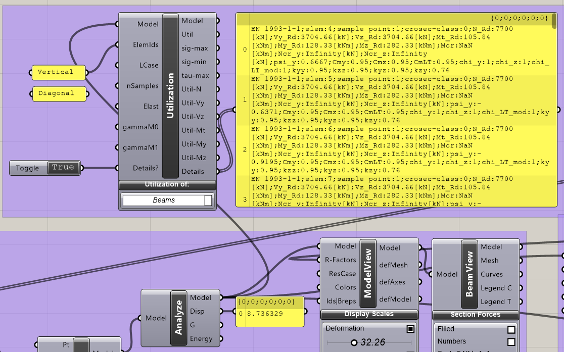
Perhaps this helps to find what´s wrong. I´ve just realized that the Eurocode3 details reported from Utilization component are a bit weird with my model. Ncr_y and Ncr_z should not be “Infinity” nor Mcr “NaN”, am I right? Please, correct me if I´m wrong since it is my first time playing with Utilization.
In your truss versions, your first buckling mode seem a global mode.
When we see this kind of deformation, its look like unstable structure (but it’s not i understand )
Personally i find this deformation very strange, that why i asked you if diagonals are connected each others or not.
But finally this modal deformation shape is very close to the first buckling mode with beams versions
The shape of the buckling mode you´ve pointed out is expected since it should be easier to displace the nodes radially than in the circumferential direction (where the diagonals would be strongly deformed comparatively). But it may be confusing that the diagonals are not joined together in my model .
I´m sorry but I disagree . Perhaps I´m wrong, but I think that a lattice structure made of Truss elements (rotations free) should always be less rigid, i.e. less stiff or experience less deformation for the same load case, than a lattice structure made of Beam elements (rotations and translations restrained). But I know that the same is not always true for strength instead of rigidity.
the reason for the difference in the buckling load factors is local buckling of the beam elements. If one uses large values for Iyy, Izz and Ipp the results from the beam and truss buckling analysis coincide: BeamTrussHinges3_cp.gh (119.9 KB)
Did you use Karamba3D WIP version for setting up the definition? The problem with the NaN-numbers in the EC3 details was due to a missing material reference. This should not happen from one ‘official’ version to the next.
–Clemens
Now, I think I understand. Please, would you tell me whether I´m right or wrong in the following points?
My truss alternative is more rigid because Karamba truss elements can´t buckle, i.e. they are infinitely rigid.
Karamba´s beam elements (even just one) appropriately consider local buckling (Euler buckling of a single beam). (I´m sorry, I though that I had to use several of them to achieve this behavior
The most detailed way to model a real truss (where elements can buckle) in Karamba is using beam elements with hinged ends.
However, the NaN numbers in the EC3 details issue still remanins, even upon updating Rhino to 2.25 and Karamba to your latest 1.3.3 version. Please, you can check it in the image or in BeamTrussHinges4.gh (146.3 KB) (this file is just your previous BeamTrussHinges3_cp.gh but with a newly created material and cross-section) Am I doing something wrong?
Sorry for so many questions, but I´ve also observed that despite the first buckling modes almost perfectly match between truss and infinitely rigid beams, the normal modes do not. Would you help me to understand why?
Hi @Vigardo,
ad 1.) The geometric stiffness for truss elements takes into account of the lateral forces due to NII at their end-points only. However they can not become unstable via the second Euler buckling case. Truss elements only take axial loads. A bending stiffness does not exist, therefore no corresponding buckling mode.
ad2.) yes
ad3.) yes
I think the problem of the definition ‘BeamTrussHinges4.gh’ is the use of internalized elements which are rooted in a WIP version. Could that be?
The normal modes are different because truss elements can not buckle in an Euler mode due to lack of bending stiffness and corresponding degrees of freedom.
–Clemens
The non-internalized version of the GH file also experiences the NaN issue in EC3 details. It is a quite large file but I can try to create a minimal non-internalized version if you think it helps.
Perhaps I´m not moving right from previous versions of Rhino and Karamba into the newer versions (6.25 and 1.3.3, respectively). I did the following:
Updated Karamba
Updated Rhino
I had to manually create again and reconnect the Material Properties and Beam View components since they were missing upon update.
I saved the new version of the GH file
The NaN issue still remained…
I realized that no “OLD” tag appeared over other Karamba components, so I did not replace them explicitly. I supposed that all of them were automatically updated to the latest version. Am I right?
@Vigardo,
when using non-WIP versions of Karamba3D, definitions created with older versions should work without modifications with newer versions of Karamba3D.
The problem lies in WIP versions where it can happen, that e.g. default values are not properly loaded when moving from one version to the next.
–Clemens
I finally found what was wrong with the “Infinite” Ncr_y issue. For some reason, I had two Modify Cross-section components sequentially connected. The first one adequately set the buckling lengths, but the second one was unintentionally removing the buckling length because it had no input connected (the latter override the former and cleared the required input fields).
I think I added such stuff while debugging the NaN issue in EC3 that probably was caused by the utilization of a WIP version of your excellent software.


 )
)