Wish: Rhino must use extended start and end planar cap surfaces when extruding curve profiles consisting quad/tangent edges. The following video reveals the complications that occur around quad regions after extruding circular profiles. Note that the ! _Cap tool is clever enough to avoid that shortcoming. The ! _ExtrudeCrv also needs to implement the same approach.
This model was created with perfectly accurate lines and circles with exact diameters each. I used 0,001 mm absolute tolerance. However, for some reason running the ! _What command reveals that the model has some unwanted deviation and gaps larger than the absolute tolerance (despite that the “Global edge continuity” claims 0 mm for every edge pair). The bug was caused after adding a single 10 mm fillet with the ! _FilletEdge command.
polysurface

  ID: 5d171ca5-259c-44f0-8800-7eaaefe7f3bc (23957)
  Object name: (not named)
  Layer name: Default
  Render Material:
    source = from layer
    index = -1

  Geometry:
    Valid polysurface.
    closed solid polysurface with 14 surfaces.
  Edge Tally:
      4 seam edges
     25 manifold edges
    = 29 total edges
  Edge Tolerances: 0.0000000 to 0.0391023
    median = 0.0000000 average = 0.0013484
  Vertex Tolerances: all 0.0000000
  Render mesh: 14 meshes  647 vertices  506 polygons
    Created with fast meshing parameters.
  Analysis mesh: none present
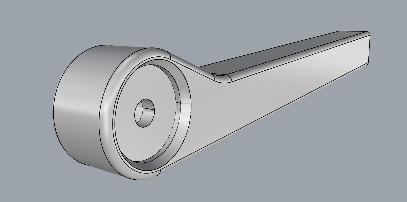
The 12 mm bore is not a true cylinder. If you make a 12 mm dia circle and extrude, you can then extract and replace the bad surface with a true cylinder that fits perfectly. fillet the edgesx.3dm (2.4 MB)
Well, then Rhino 7 must be fixed with a new Service release, because this particular bug is super annoying and must not occur at all! The aforementioned surface was a true cylinder originally. I added the 0,7 mm chamfer next to it, then moved its the inner edge by 0,5 mm to make the chamfer 1,2 mm deep. Seems like this simple modification caused some confusion to Rhino, hence it split the cylinder into 4 quarters.
Thanks for the tip! I will mark your reply as a solution as soon as “McNeel” staff takes a notice and adds this bug to the pile. Preserving the original surfaces during simple editing like this is a must!
P.S. I actually have a mirrored version of that very model which does not have the cylinder split into 4 quarters. However, it also refuses to accept fillets… For some reason the original model uploaded in my first post has a split cylinder whereas the mirrored copy doesn’t.
Another similar unwanted splitting occurs when a true cylinder is offset as a solid. Then Rhino splits it into two halves, deleting the original cylinder forever without a notification.
I just built your part from scratch and this edge move worked fine and didn’t mess up the cylindrical surface. Got to be something more to it so I probably built it in a different way to you… Can you do this again and reproduce the error, recording the exact steps used to do so?
I’m guessing you used one of the solid editing tools. Those tools are garbage they will eventually destroy your models. If you use these tools it is surprising that you have not run into problems like this before now.
Rhino split the cylinder into 4 pieces because the 4 quarters were no longer tangent after you edited the model.
This second model has the same defective12mm dia. cylinder as the first.
If you use Rhino’s solid tools you should expect to have problems. You can build your model without ever using anything in the solids menu and learning to do it like that will give you reliable and accurate results.
Is solid modeling tools causing this problem based on testing of this situation, or speculation based? My understanding is the solid modeling tools use the same methods for basic geometry alteration s other tools such as Intersect, Split, Trim, OffsetSrf, etc.
Yes of course. That is my point, you don’t have to rely on the solid tools to do any of that. If you want those operations done consistently accurate and to avoid downstream problems you should avoid letting the solid modeling tools do them. The example given in this thread is just one of numerous examples. I have pointed out such examples that have been posted here numerous times over the last couple decades.
Bobi modeled this using solid modeling tools. What one has to guess about is where in the process things went haywire.
IMO, this is the main reason the surface modelling tools are far more robust than the solid modeling tools. Over the years bugs have been reported over and over and since no one can figure out where in the solid modeling process things go bad the bugs rarely get addressed. With the surface modeling tools the errors can be readily found, reported and fixed. I know this because I myself have reported dozens of bugs over the years that have promptly been pinpointed and addressed.
In Bobi’s example there may be more than one bug but I doubt they will be found or fixed.
Unfortunately, I don’t remember the exact order in which I modified that model, but the last two operations were (not sure which was first and which second):
Adding a 10 mm fillet on the top wall;
Adding a 0,7 mm 45-degree chamfer to the round hole, then Sub-object select (Ctrl+Shift+LMB) its inner edge and moving it with the Gumball (dragging the X-axis arrow handle and holding the LMB while typing a distance of 0,5 mm) to become 1,2 mm in one direction.
I usually work with surfaces when I design car chassis with round pipes, and never modify polysurfaces this way (especially if they already have fillets), because the structure of certain surfaces gets destroyed without a notification by Rhino and then the originals are forever lost. However, I thought that this ractangular extruded model is simple enough to accept a basic modification such like moving a single surface edge. I was wrong.
I occasionally modify boxy models this way, but never had such an issue before that will prevent me from further selecting edges to add fillets as the last operation. Rhino didn’t reported that this is a bad object either.
Typically I use a profile curve which I revolve to make round holes with complex shape, but this particular pocket was not intended to have a non-symmetrical chamfer. I decided to modify it later, hence I didn’t used a revolve for it.
Here is the entire file consisting the profile curves used to extrude the body, along with the circle used to extrude the round hole. They are all hidden, so you have to unhide them again. Стойка за телефон 1.3dm (3.2 MB)
P.S. The visible geometry in the file is a phone stand for 3d printing consisting two pieces that need to be glued together via super glue. I made it this morning from PLA and it works perfectly fine with my 3 “Samsung” phones with various sizes and silicone cases (S10e, S24 Ultra and A52s), so feel free to 3d print it if you wish.
Photos:
Yes, the edges of the surface are a precise 12mm dia. But the surface is not. That’s why you can replace the bad surface with a good 12 mm cylinder and it will fit perfectly.
It is typical of the solid modeling process that you don’t find out that you are screwed until much later.
Trimmed edges partially coinciding with the underlying untrimmed edges of the surface have been causing problems since at least V4. They do not always cause problems; for example if the trimmed edge is an isocurve. This is the reason for both the ShrinkTrimmedSrf and ShrinkTrimmedSrfToEdge commands. The forner leaves a small margin from the trimmed edge unless the trimmed edge is an isocurve. That small margin eliminates the possiblity of problems due to the trimmed edges coinciding the untrimmed edges of the underlying surface…
The edges I changed are not edges of the 12 mm cylinder. I left those edges unchanged. See my step-by-step description and images.
The issue of whether the 12 mm cylinder is an exact 12 mm cylinder appears to be unrelated to not being able to select other edges for filleting.
All you did is kick the can down the road. The 12mm cylinder is still bad. That bad surface is what derailed the brep’s edge definitions that led to the failure. That happened when an edge was filleted far from the defective surface. The model is likely to run off the tracks again if future operations are needed.
To fix the original model all that is needed is to extract the bad surface delete it and replace it with a proper 12mm cylinder. The easiest way to do that is to extrude one of the 12mm dia. edges. After the good cylinder is joined to the rest the edge selection failure goes away.
Actually all you have to do is extract the bad surface and the edge selection problem goes away, but then you no longer have a solid.
Exact untrimmed surface size is typical for when curve profiles are used to extrude the desired shape. Rhino should be able to properly interpret the curves to create polysurfaces from curves avoiding gaps and splitting arcs and circles where they are tangent to the trimmed surface edges. I have created thousands of similar extrusions in my life and have never experienced this particular bug.
Extrusions like this are not an issue as long as you don’t modify the resulting polysurface. On rare occasions those arc regions may lead to splitting the edges of planar surfaces, but I see a split cylinder into 4 quarters for the first time in my practice. Usually Rhino splits the cylinders into two halves when doing a solid offset (if I remember correctly, Rhino 5 didn’t had that super annoying bug).
However, if a polysurface has a planar opening and the ! _PlanarSrf command is used to fill the hole, Rhino usually creates a slightly larger surface than the border of the input geometry, which in turn helps to avoid bugs with split tangent edges around fillets or arc extrusions.
Both, the flat planar surfaces (start and end cap surfaces of the extrusion) and the modified cylinder (after adding the chamfer to it) cause problems in my model. The solution is to replace the two cap surfaces with new ones consisting slightly larger border, plus replacing the cylinder and the non-symmetrical chamfer (0,5 mm by 1,2 mm) with a revolved profile. Only then the model is 100% clean to be further modified with no issues (until a new bug occurs, because this is Rhino after all, and random bugs are part of the fun ).
alternatively to build the surfaces cleanly and not do whatever unnoticed step messed them up - which in this instance has nothing to do with whether surface or solid modelling was used.
Just for fun I remodelled the object again four times using different techniques. All have clean surfaces and tight tolerances, and edges filleted happily. No surfaces needed replacing or enlarging.
The purple object was modelled “without using the ‘Solid’ menu” (apart from _FilletEdge at the end, as with all the objects).
The brown object was modelled using solid modelling with extruded ‘cutters’ boolean differenced from a solid body to create the holes.
The grey object was also modelled using solid modelling, but with polysurfaces rather than extrusions.
The green object was a late addition modelled primarily using surface modelling but taking advantage of new information from Bobi to more closely mirror his actions. The 10mm radius in the top was applied as a fillet instead of using a curved profile; the chamfer was applied as an equal chamfer and the inner edge was sub-object selected and moved inward by 0.5mm as he had done.
The only differences resulting from the various techniques were:
Either one or two edges between the chamfer and the cylinder, depending on whether their seams aligned or not (to be expected).