Thanks for the response @DanielPiker. I was hoping to define the x, y and z dimension in the gyroid.gh definition I sent for a regular Cube without trimming. I noticed the dimensions I get for the entire model is different from what in put in at x, y and z. Is there a way to create say, a 10mm x10mm x10mm box of gyroid?
Can you create a BoundingBox of your final Gyroid cube, DeconstructBox to get the X,Y and Z dimensions and then Scale NU to get it to the size you want?
Your definition probably sets the X, Y and Z for the initial mesh and the final size is dictated by everything that happens after that.
1 Like
@martynjhogg can you help me out here? I’m finding it difficult to make it work
I can’t open your Gyroid.gh file because I don’t have Millipede but the attached file takes a mesh and scales it to be 10.0 in X, Y and Z directions.
SCALE_NU.gh (10.8 KB)
Many thanks to Daniel Piker

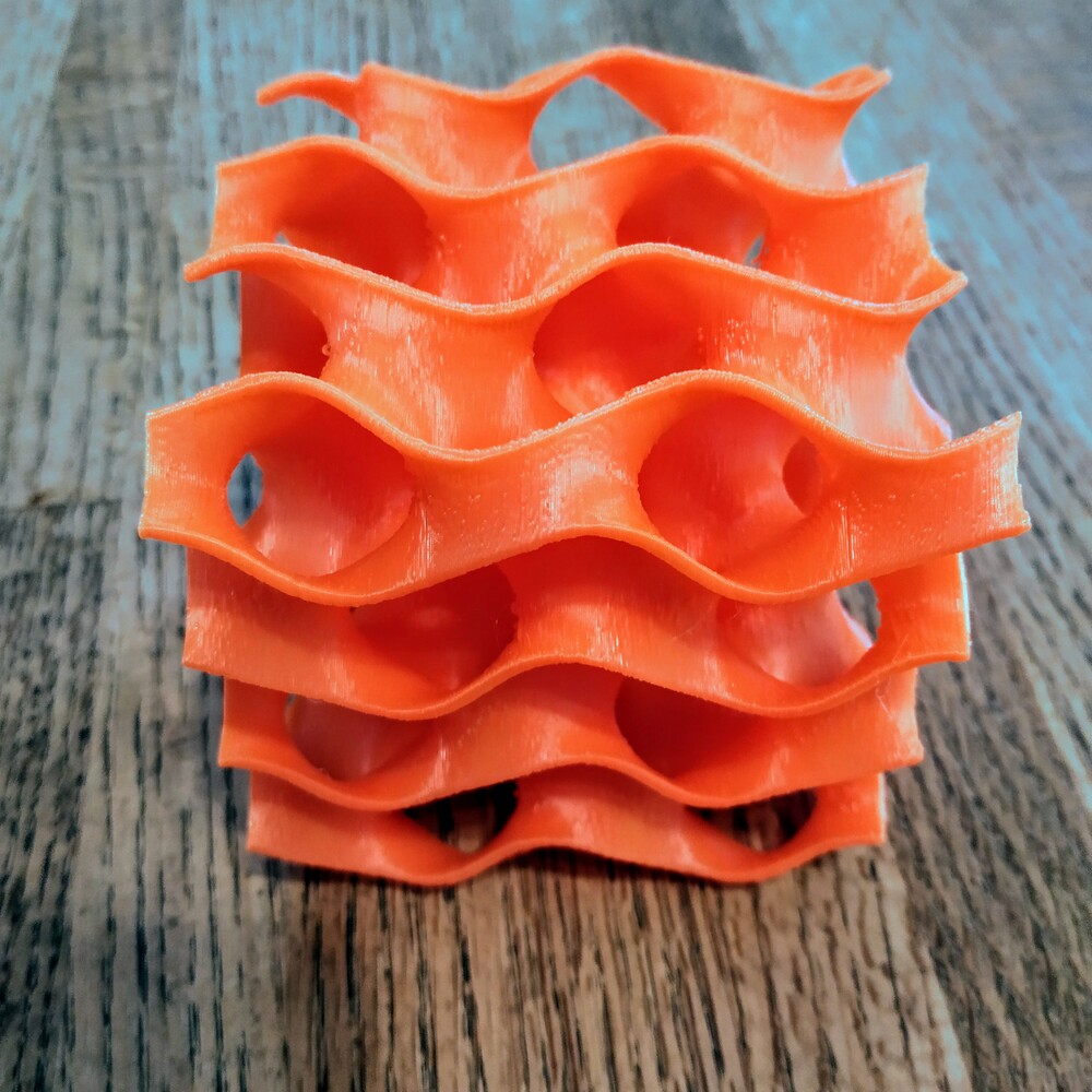

And here’s a 32 sec. video: Minimal1
Needless to say I could not have done this myself - what I did was take Daniel’s GH file and tweak it a bit to make the object 3D printable. My first attempt to print failed because no side of the geometry is truly flat, which means there were only tiny points of contact with the printer’s print bed. These points were not large enough to hold the part in place. So I whacked off a small amount of the bottom of the geometry and made it flat. This allowed the print to complete in 7 hrs. 52 min.
Daniel was generous enough to post an alternate design, so I combined that with the first one and added some GH components to do the bottom fixing. I’ll be happy to post the whole GH file for anyone who’s interested, but it requires some explaining because it uses 3 separate solutions.
The STL file for printing is here: Thingiverse and Pinshape.
3 Likes
@martynjhogg THANKS A LOT!! I have been able to define the dimensions with your example. Thanks for the amazing support
1 Like
Hi Daniel, Thank you very much for pointing me to this thread. Great results! I’m curious if you have any tips for cleaning up the mesh edges when you follow this minsurf_trim.gh method, as the cutting produces rough geometry when thickened. I’ve tried most of the weaverbird subdivisions and smoothing objects at various steps in the process without much luck.


@DanielPiker I wanted to echo @grasshopper 's question above - is there a better way to get clean mesh edges after cutting a gyroid array?
Using the definitions above, the cutting results only roughly match the geometry of the cutting mesh.
Thank you!
Here’s an example of the jagged, invalid mesh that results from using the above trim script.

Hello Daniel, I am currently working on a research on ways to discretize TPMS into strips for fabrication purposes and @enriquesoriano shared this link with me which happens to be an extremely elegant solution you had posted a while back, unfortunately it was on google plus which has disappeared, can you please share the algorithmic thought process.
Hi everyone, I know this thread is old, but I hope I can ask for help. I’m working on generating minimal surfaces via the Koebe polyhedron method, but despite the scripts already shared, I still can’t get it to work. This is my GH file — I’d be very grateful if you could take a look and offer guidance when you have time.
Or, if someone could provide the principal curvature lines network of gyroid surfaces, I would be very grateful