Hello,
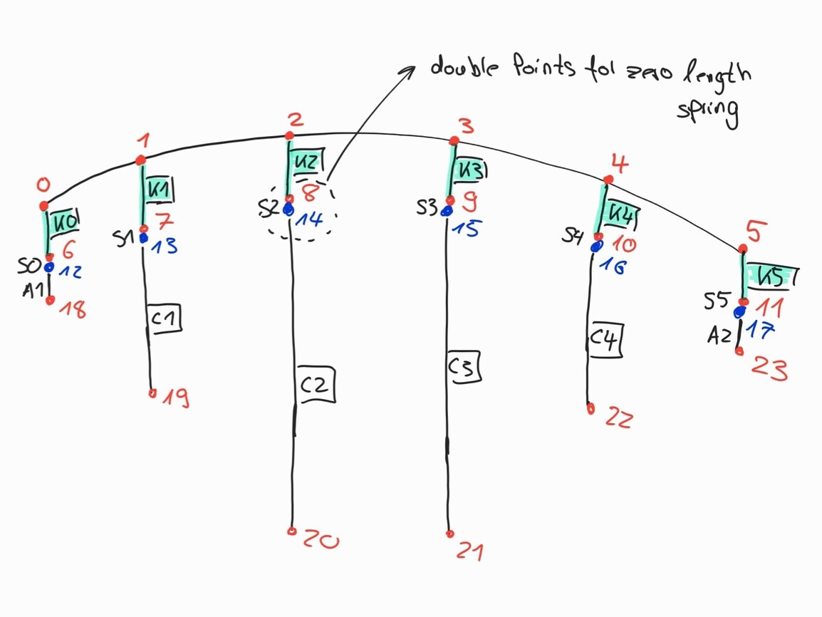
I have a bridge model where I have difficulties with bearing. The bridge has 5 fields. The two middle pillars are fixed pillars (translation in x,y and z locked). The two outer pillars allow a movement of the superstructure in the x-direction. At the abutments the bridge is also movable in the x-direction.
Between the superstructure and the pillar are rigid coupling rods. Between the coupling rods and the pillars are springs with a zero length. Same principal at the abutuments with shorter rigid rods.
Problem 1:
- The springs cannot be rotated in such a way that only a displacement in the x-direction of the bridge axis is allowed (“z-orientate” in the component “index to beam” and “orientate element” did not work or I probably applied it incorrectly)
In the GH file, the springs are currently incorrectly rotated (Top View):

How it should be:

Problem 2:
- The torsional bending moment is not correct at the moment (Load Case 0). It actually had to look like this:

Current appearence:

Here I have already tried a lot of spring adjustment, but I could not find a solution.
Does anyone know how to adjust the springs correctly or whether you generally have to model them differently? I would be very happy to receive support 
Tangential bearing.gh (85.6 KB)