I am running Ver 7 with Bongo 2 and I am very new to all of this. I usually don’t bother people for help, but I have 20+ hours into trying to figure this out and I am lost.
I am trying to create an animation of a multi section tubing with one end fixed and the opposite end controlling bending and position of the entire tube, similar to a snake with its tail in a fixed position. I have set up an IK chain and fixed it to the stationary element, but I am lost at making it work. Maybe I can upload my model when I am approved on the site. Any help out there?
I am trying to create an animation of a multi section tubing with one end fixed and the opposite end controlling bending and position of the entire tube, similar to a snake with its tail in a fixed position. I have set up an IK chain and fixed it to the stationary element, but I am lost at making it work.
The model that I have attached should have 37 elements of the hose plus a filter and nozzle. I made a shorter model for the upload. I want to unwind it and position the nozzle and the nozzle would follow a path.
I made the nozzle the topmost parent in the chain. This is so I could use a look along curve normal constraint as the path it would follow. The last item in the chain is a dummy point constrained to another point. This makes it easy to move around the end position of the tube, but you could also just use the “Keep pivot location the same.” All the links are joints allowed to rotate on the X, Y, and Z. I removed the limits since they complicate this model and make finding a valid path a lot more difficult. This setup should show you how structure the IK chain so you can add the limits later.
It’s not perfect. As you can see certain objects clip through each other. The limits should help with that.
If you haven’t seen there are a host of tutorials on Bongos website. These may help you understand the IK system better.
Joshua, Thank you for your help. I am trying to work with the model you sent to get the result I am trying to achieve. I am having hard time getting the last piece to be stationary. It fits into a flange and must not move. Here is another model with the flange in place. I can see that I have a lot of work to do to get the behavior that I want, but it is great to see how you put this together, ThanksCone, Tube and Filter Example 2.3dm (18.1 MB)
In order to keep the final node stable, you have to alter the Constraint of ‘End Point’. A constraint to another object only controls its Position but not its Orientation nor Scale. Instead ‘End Point’ should be constrained to the World. Hence it is possible to select its degrees of freedom. By allowing no freedom at all (leave every Relax boxed unchecked) the object stays fixed!
Please allow me a remark. When I looked at Joshua’s model I was wondering how he defined the exact location of the Hinge joints which connect the nodes. Making a cross section of 2 nodes
I noticed not only that the volumes interfere (the small part is to large to fit into another node) but also that their design, the degree of the curvatures, do not take into account the possibility of rotation. No wonder “certain objects move clip through each other” like Joshua noticed. No limits can cure that.
I feel you need a different design, that at least allows some rotation between the links. Maybe something like this ? Snake Like 000.3dm (2.2 MB)
Luc
PS I used the circles in ‘Snake Like 000’ to define the exact position of the Hinges.
Thank you, but all of the relax constrains are already unchecked and the end point and constraint point still move. I have tried many other things to make this work and every time I reconnect an IK chain to an object it take several minutes to never for the precalculation to occur. I just di one that sat for 3 hours and never finished. What kind of specs do i need for my machine? I have 32Gb RAM and an I7 4 Gb processor.
In my personal experience the IK solver takes (or seems to take) for ever when a “Constraint goal not reached” is on its way to appear.
The amount of Joints seldom causes extremely long calculation. The amount of Constraints however lays a heavy burden on calculation time. When calculation on my 3.20 GHz CPU machine takes more than 13 minutes (even on a complex mechanism) I’m persuaded there is something wrong in the conception of the IK chain, or in the implementation the IK elements (e.g. the wrong orientation box of a joint checked). Then as I have established that all those thing seems to be OK I know I have to investigate whether the theoretical base of design of the machinery itself allows the expected operation.
It’s not always IK’s fault.
Maybe @marika_almgren can tell you more about machine specs. I’m not eligible on that matter.
The specs sounds fine. Bongo has the same specs as Rhino. Rhino - System Requirements
The problem sounds more to be model based than machine based. If you have a model that takes that long to calculate there’s something wrong with it.
If you’re able to share it, please do and we’ll take a look at it.
I got the tubing to work OK except that I would like to know if I can control the positioning of the body of the “snake” between the nozzle and the fixed point. I also want to have the nozzle start face down flat on the table surface, then rise up and follow the path. Does this have to be done with two sequential paths? Also, at the completion of the animation, the tube wobbles like a snake. I want it to just stay in position. I can’t attached the file, how do I send files that are larger than the allowed amount?
I am having issues with another section of my project. The file is 33 mb so I can’t upload it, so here are some images and description. Thank for any help you can offer and any way that I can upload the entire file.
Rich
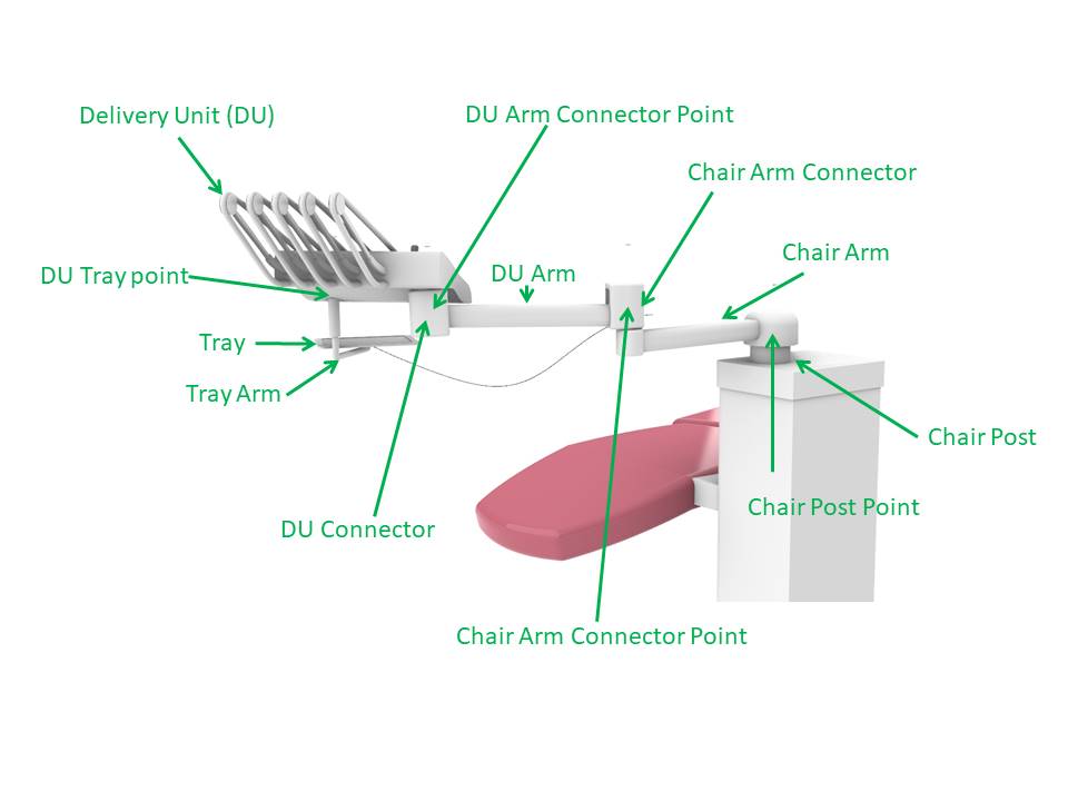
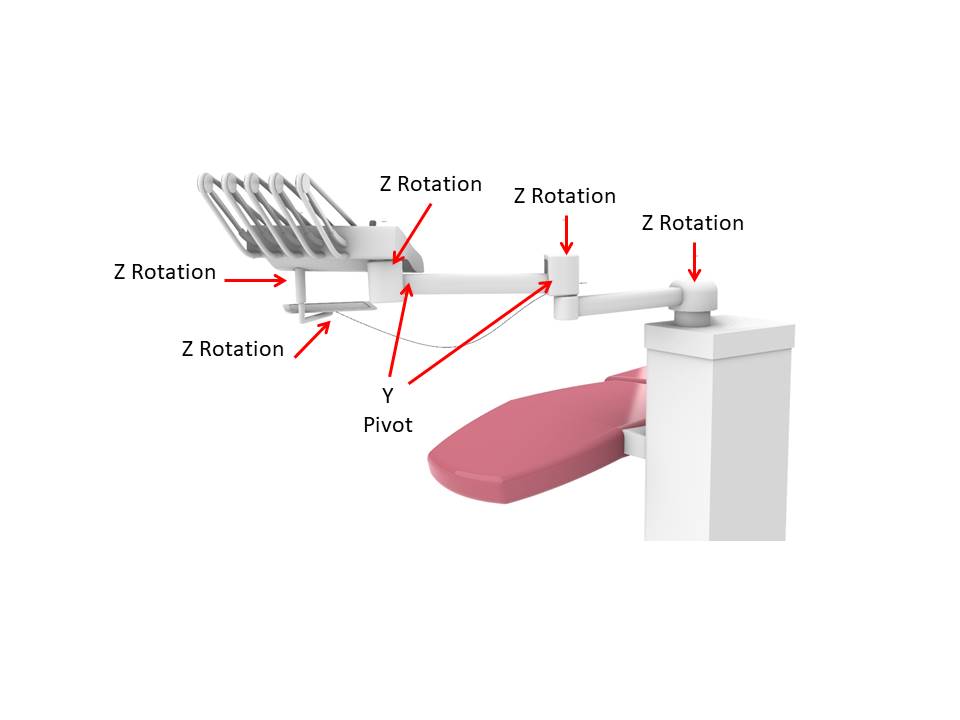
I am getting some insight into how all of the IK works, but my joints keep falling apart and I can’t seem to fasten the end point. I used the same parameters as the tube animation, but the end still won’t stay stationary. Here is what I am doing. The tubing is part of this larger animation. I have identified the IK Chain below with the names of the components in the IK Chain. The Z rotations are “Z” Hinges with no constraints. The two Y pivots are “Y” Hinges because that are is supposed to move like a teeter-totter, and I connected in IK with points.
Luc,
Thanks for the advice on the parts. The animation that I was able to create works well enough for my purposes now, but I will look at a re-design as well. I looked at your example, but I can’t tell what makes it move.
For Object 0 (the head of the chain) the Position and Rotation parameters are animated.
Looking at the images the scheme of the mechanism seems fine. Since it has kind af a Robotarm mechanism I wonder whether it would be better to build it the other way around. With the chair post at the top of the chain and a “pulling driver” at the end.
But yes … a model tells more than thousand words. I feel the most comfortable way to send large files is by using WeTransfer.com. It’s free, it’s simple. You can send to my address luc@mcneel.com.
By the looks of it you got somewhat confused, and mixed up the techniques of ‘shaken by the head’ and ‘pulled by the tail’. That’s obvious the reason why you get the feeling your “ joints keep falling apart”.
In the model you send me the position of the pivots of all the objects is perfectly fitted for them to function I a ‘pulled by the tail’ structure. On the other hand is the top to bottom structure of the chain suited for a ‘shaken by the head’.
Your device is clearly a basic Inverse Kinematic structure, similar to a robot arm. Such is by default a ‘pulled by the tail’ system.
So in the model “Delivery Unit And Arms 001.3dm” I reversed the entire Hierarchy hence making “Tray Point” the end (the tail) of the chain instead of the head. No pivots were relocated, no joints redefined. For “Tray” the Simple Constraint was omitted since no constraint was defined. The objects “Chair Post Point”, “Chair Arm Connector Point”, “DU Arm Connector Point” and “DU Tray point “ are superfluous – they were simply deleted.
Then I made “Chair Post” a Hing Z, and IK-constrained “Tray Point” to “Path Point”… and bingo, no more joints falling apart.
Remains the matter of “DU Arm”. I guess it is not the intention to let it rotate along its Y axis?
Its shape suggests that the link is meant to shift up and down, hence allowing the tray to follow the variation in height of its path. And I suppose the same goes for “DU Connector”.
So by means of illustration, in model 002 both objects are made a Telescopic Joint Z. Apparently the height of the tray varies too much for the arm to deal with?!
Thank you again for spending the time on this. Your model 001 works the way I want except for the DU arm. It moves correctly on the Chair arm connector in that it moves up and down with a Y pivot. However, the DU Connector does not work the same way. The DU connector and the Chair Arm connector should always stay parallel to each other with the DU Arm allowing the up and down motion without altering Y axis rotation. I have Tried a number of options on the joints, but I can’t seem to find the right combination. I will keep experimenting. I attached an image that shows what I want to achieve.
A solution to have sequential paths is to make the first path child of an auxiliary point which performs the travel along the second path.
Sounds somplicated? Better take look at this model: Sequential Paths.3dm (107.5 KB)
As for your ‘Delivery Unit And Arms’: in order to keep the part ‘Delivery unit’ horizontal - like in in your image above - a parallelogram structure of Hinges is needed, such as in a industrial table lamps like this .
But the part “DU Arm” in your model is one piece. Hence it does not provide the parts necessary to make a parallelogram of Hinges. At least the part should be split in 3 separate pieces to allow such action.
Indeed, the picture of the lamp served merely to illustrate what I meant by a parallelogram of Hinges structure. Delivery Unit And Arms 003.3dm (2.8 MB) is a schematic application of such parallelogram in your device.
You’ll notice it is not exactly a simple IK application. Rhino - Bongo™ deals with this matter.
The paths themselves are not collected. The first path curve (Object 55) is made child of an auxiliary point (Object 26) that is Simple Constrained Look Along the second path.
The pyramid is Simple Constrained Look Along to the first path. It travels from bottom to top during tick 0 till 50. Further on it simply stay at the top of path object 55.
During tick 50 till 100 the auxiliary point (Object 26) travels down along the second path. Since the first path curve (Object 55) is child of this point it travels along, and since the pyramid is constrained to it (at its top) it also travel along. Hence it looks as if the pyramid travel along the second path as well.
In order to get the movement smooth the end of both path curves kind of coincide. Therefore the last 2 control points of both curves are aligned.
I hope studying the models will enlighten your understanding of IK. But don’t hesitate to ask if you have any more questions.
Luc
PS I deleted all the unnecessary objects (kept only the ones involved in IK) and also all the materials. Thus the file size of the model remains below the limit.
Hi Luc,
I finally gave up on the parallelogram aspect of the arm. I tried hundreds of combinations, but could not make it work. It is not critical to my animation, but this problem is. I am back to the tube problem. I can get the tube to animate, but I cannot control where the cone starts and stops. I have uploaded a model to We Transfer.
Please Help!
I am going insane with this problem after hundreds of attempts and dozens of hours waiting 45 minutes between IK chain pre-calculations.
I am trying to get the Cone at the end of the tube start where “Object cone” is at tick 14. Then I want the cone, filter and tube to follow the path of the Object cone through to tick 43. I cannot control the coiling of the tube at the beginning rest position, and I can’t control the rotation of the cone attached to the tube to make a realistic coil-uncoil movement. Once I do get to the animated location of the Cone/Filter, I can adjust the X,Y,Z in the linear dimensions but I cannot control the rotation in any axis, it just keeps bouncing back to the original location.


 :.
:.
 .
.