With the structure I created I have 150 different connecting pieces which I need to mark somehow to be able to tell which one belongs where. Since I haven’t been able to label each piece I tried to mark each one with a small spehere on one side of the piece, to be able to know which side belongs up and where’s left and right.
The problem is, that now I have the spheres on both sides. I tried using cull pattern and cull list to only have one point on each piece but it didn’t work out for me.
A different problem is that I wasn’t able to set one point where my sphere sits, so I used the populate random command to have a suitable point for my sphere, which is not working 100% since it’s random and sometimes blocking the intersection.
You can see what I mean in the picture / file I’ll attach.
Afterwards I need to orient each piece manually on the cplane with orient3pt in rhino, or is there another solution? Since I still need to know which piece belongs where.
Hi.
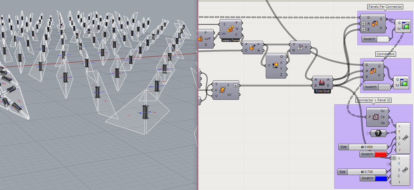
I’m not sure what are you going to do, anyway, to me, this is mearly a problem of applying proper id tags to your connectors.
You can use Brep Topology’s Edge/Face adjacency tree data…
Though I still need to idenfity the orientation of the printed connectors afterwards, that’s why I used the spheres.
Without having a mark on each connector I don’t know the orientation, and neither if it’s the right or left side of the connector, so I have four possibilities to make a mistake assembling the pieces.
You have already given edges and you can use them to get perpendicular or horizontal frames for orienting your connectors.
If you want to know the connectivity relations with the panels, it would be easier to orient each of the two panels to be connected per frame together when orienting a connector.
Could you explain what you mean?
I’m just at the beginning of understanding the complexity of Grasshopper and Rhino so any explanation which helps me understand certain things is highly appreciated
In addition to the suggestions provided, you may also want to consider how you will be 3d printing them, (Extrusion, SLA, Fused deposition modeling (FDM), etc…). As well as if you are doing it yourself or sending it out. If you are doing it yourself, you might have a little more wiggle room to “cheat” by tracking parts as you print them, but this is not really a great idea…
If you are sending them out to a 3d Printing service, you will absolutely need to come up with a labeling scheme. The reason is that, (most times), a printing service will “nest” all your parts together using a nesting algorithm, that doesn’t care about part order. If each part is unique, but similar, it will be absolutely necessary to have some identifying element.
We had a few similar discussions on the old GH forum, (Maybe search there as well?).
One idea was to add a “disposable/removable” element to each part. Something that could be clipped off easily after printing. Would add a little bit more to printing cost, but maybe a solution if you don’t want to leave artifacts on the finished parts?
I’ll be 3D printing them myself with the hephestos 2 my university has. So I can track and organize the parts while printing, but thanks for the information and the input
What do I have to change on the “orient command” in order to have the connecting pieces standing upright?
It’s just the final touch, otherwise I can do it manually.