I have a triangulated tiger model. I remeshed into quads. I want to 3d print as pieces of planar quads. I have seen alternate planarizing solutions. I wonder is it possible planarize all the quads without having crippled ones? Or if it is not possible I could use very few triangles where the planarizing fails? Can it be achieved without manual work?
tiger.3dm (588.8 KB)

paging @DanielPiker
Paging is a function of memory management where a computer will store and retrieve data from a device’s secondary storage to the primary storage. Memory management is a crucial aspect of any computing device, and paging specifically is important to the implementation of virtual memory.
???
verb
gerund or present participle: paging
- summon (someone) over a public address system, so as to pass on a message.
“no need to interrupt the background music just to page the concierge”

planar_tiger.gh (192.0 KB)

I wonder though, if you are 3d printing it, why would they need to be planar?
4 Likes
There was a nice example by @DanielPiker in this thread that planarised a polar bear mesh (albeit lower resolution)
planarize_bear.gh (17.3 KB)
I tried it on your tiger mesh but unfortunately it “cripples” some quads. Perhaps there are some other goals that can be added to stop this happening?

In my example above there are anchors and length goals that prevent most of that crumpling, but ultimately you are limited by the mesh.
If the input quads aren’t well aligned with the curvature, then it’s just impossible for them to all become simultaneously well shaped, planar and close to the input shape. No type of optimization of vertex positions is ever going to change that.


I thought if triangles included where there is no good solution, solves the issue. It does not? Is it recognizable by the definition?
The flat surfaces is need beacuse only the first layer looks really nice be FDM printning, and that would be the outside.
I don’t see a way of automatically replacing quads with triangles where the quads become distorted due to planarisation.
I see why you want planar quads for the FDM process… the outer face would be the first layer or last layer printed to give a decent surface finish.
Are you aiming for a planar, conical mesh so it can be offset, printed as thickened planar quads and then glued together?
Hi @Balazs
Did you open the file I posted?
I also included there the internalized planar mesh result at the end so you don’t even need to run the optimization yourself.
That’s already all quads, all planar, and without any self-intersecting or degenerate faces.
There are 3 or 4 concave quads around the left ear but even those are still valid planar faces.
1 Like
Hi Daniel,
Thank you very much for the solution. It is really amazing! I see on the curvature window the deviation from the planarity?
I thought if it is below half millimeter, the 3d printed plastic can “eat it up” by distortion when I am connecting them to each other. But I guess I have to make them mathematically planar every single peace so that I can print it the stl.
How can check the deviation of a single quad?
By the way should I see any change on the model when I am moving down the slider to zero? What it the other mesh? is it the final mesh output? It it the and state when the slider is set to zero?
I think you are also going to have to think ahead to how you are going to thicken this mesh, split each thickened mesh face into separate pieces to print and identify them so gluing them together does not become the worst jigsaw puzzle you ever did! 
@DanielPiker has posted a neat way of planarising and conicalising a mesh so it can be thickened using the Kangaroo Face - Face component and then you can work out how to ID each piece.
I believe the Ngons plugin by @Petras_Vestartas can be really useful for this too along with creating dovetail type edges.
Thanks for the suggestion but actually my solution to handle the elements( thickening, id, conection, etc) is ready and in fact I am using NGON for that. Big thank for Petras Vestartas fot his plugin and for his help. Now I only need the elements. If is not completely flat mathematically probabaly should not be problem. I can make them flat one by one. It would be nice if I could colorize the the mesh showing the curvature same fashion as the little curvature window, what Daniel did.
Isn’t that done in Rhino from the Analyse >> Surface menu? On phone so can’t check but bake mesh into Rhino then analyse maybe
As Martyn says, one way is to simply bake into Rhino, use ToNURBS, then Analyze>Surface>Curvature Analysis
Here’s a component though for if you want to see the planarity display on the mesh updating live in GH.
planarity_display.gh (96.0 KB)
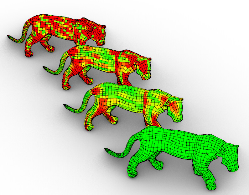
It uses a common measure of planarity as the distance between the diagonals of each quad, divided by the average diagonal length.
So for instance a square panel with a 1m diagonal and a 1mm distance between the diagonals would return a value of 0.001.
The input max slider value controls what planarity value maps to red. So for instance, if you have 10cm panels, and you know they can twist up to 2mm, then set max=0.02 and the ones shown as red would be at the limit.
Even for architectural scale tempered glass panels you can usually cold bend a few mm without problems.
Here’s a nice example of planar glass panels done with Kangaroo
For something like 3d printed plastic panels, I expect it is much more forgiving - you could likely get away with orders of magnitude higher twist.
(in the example optimization I posted, even the most twisted panel has a value of less than 0.000001 after convergence, so way stricter than needed)
I used to have a version of this planarity display as a component included in the old Kangaroo, I’ll add it back in to the next release.
8 Likes
I am trying to use the the planarity display definition on a mesh which was genrated by quadremesh. The mesh appears to be OK, and I also ckecked it meshrepair. However I have got an error meassge and nothing happens. What is the problem?
planarity_display_20220422.gh (53.5 KB)

Look at the scale of your object…

Mesh edge length between 0.007258 and 0.108391
I scaled your object with a factor of 100 and this is the output:

planarity_display_20220422 (1).gh (65.9 KB)