I want to create a mesh/surface from contours that I imported from CAD with Z-values. I wonder what the quickest way is to create a surface from these contours? I prefer not having to use Grasshopper due to time constraints of learning a new program.
1. Select the curves and turn on points (F10)
2. Select the points (_SelPt)
3. _MeshPatch
(see better instructions below)
I do not recommend running MeshPatch on the polylines themselves but rather on their control points. Running MeshPatch directly on polylines may cause Rhino to hang for a long time while it tries to calculate… something. The result is the same in either case. Using just the points is very fast.
Thank you for the fast and clear answer! I turned on points, selected them and got to MeshPatch. I select no holes, press enter. Then it says “Creating mesh… Press Esc to cancel”. But there seem to be no processing happening, and by CPU/GPU have resting temperatures. Am I doing something wrong?
You can run _Patch instead of MeshPatch on the points - that will give you a surface instead of a mesh. However, it will not go through all the points as the MeshPatch does, depending on how many spans and what stiffness you give it will determine how much it conforms. A lot of spans and low stiffness will conform better to the points, but will also make the surface heavier, noisier and harder to edit globally (but better to edit locally).
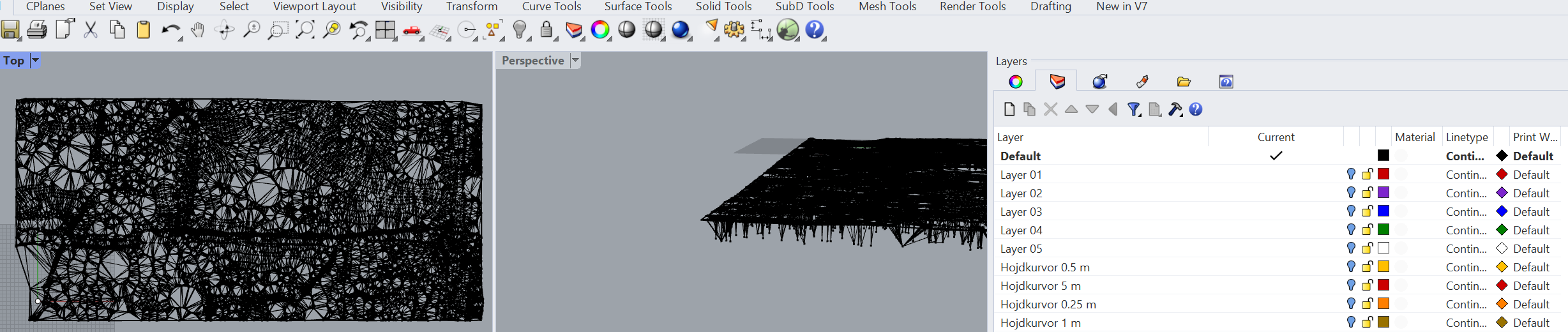
From your image above it seems you have a number of points that are well below the average level of the rest - is that how it’s supposed to be (these are ‘holes’) or are these points at the wrong level?
Alright, I am trying with the Patch command instead. However, increasing spans and lowering stiffness created some crazy results haha.
But local edits is what I want to do with very fine nuances. I am working with a 0,25m height difference between the contours, in total around 4m from lowest to highest point on map.
The points below the rest maybe is the problem. Maybe there were caused because I was deleting a lot of points outside the area. Which I did because the trim/split tool would not split/trim the contours, maybe they were too complex.
Well, after having fixed the point problem, you can run Patch playing with fewer spans and varying the stiffness until you get a terrain result smooth enough yet close enough to the original that is acceptable to you. Then Rebuild the patch with many more spans - which will allow you to edit it more locally. Again, some experimentation will be necessary.
I would use the drape command instead of patch, it gives a cleaner output and does not overshoot beyond the input geometry. It basically drags a surface over the mesh.
Hey, thanks for the tip. I tried using Drape by selecting the area of the point clouds from ExtractPt. But it does not seem to work, nothing happens. What am I suppose to drape?
You can drape over the MeshPatch. It’s another way to have a surface instead of a mesh. You will most likely need to turn off automatic point spacing and experiment with the U and V point counts to get something that works for you.
Thanks bud!
Here is the result of the ditch from MeshPatch only. I wonder if it is possible to just create a surface based on MeshPatch, and then edit that one? It seems both Drape and Patch works with square grid pattern, which perhaps is bound to be less exact.
Edit: it became 250 V here, but result is similar with 500V.
Patch is more exact with lower U and V values, but still is floating in the ditch. It seems like it takes more computing power to run it. Maybe because it is a bit more exact. Patch also creates random hills around the ditch. Not a huge problem though.
I got one final question about how to create new elevations in the Draped square grid. In this video the guy uses RebuildSurface and then PointsOn, which enables him to see the points in each intersection in the square grid. When I try to do that for the Draped square grid, nothing happens. I am wondering if I still need to create some kind of surface to be able to do that?
Sorry, I forgot to mention that you could use the Delaunay mesh component in Grasshopper first with the pointcloud as input. Then you have a mesh you could drape a surface over. But I see you’ve figured this out now.
If you can’t get the drape to be detailed enough, you may need to increase the precision on the mesh. I don’t think you can get it any more precise than a delaunay mesh. If you are new to Grasshopper, don’t be scared, it’s just referencing the points into the Delaunay mesh component and bake the result.
Yes, both Patch and Drape make surfaces with rectangular UV’s, the difference is that Patch will try to determine some 'best-fit" plane for the orientation of the rectangle, whereas Drape will always be rectilinear with respect to the CPlane of the viewport the Drape is drawn in. Patch will allow you to use a starting surface to determine the UV orientation of the result, you can sort of control the Drape direction by rotating the CPlane in the viewport.
In both cases, as mentioned above and as you found with the ‘ditch’, smaller details are bridged over because there are not enough sample points and the points are not always in the right places. That is why meshes are usually preferred for terrain models.
You might want to look into adding rows of points in U or V or both using InsertControlPoint to increase point density in some areas for post-editing.
One other approach is to make a surface which best corresponds to the largest part of the mesh, and then instead of trying to point edit the smaller detail areas where there are not enough points, trim those areas out, make new smaller local surfaces that conform better, then adjust/join those to the original. This will of course then end up as a patchwork kind of affair and it will be a polysurface - one that you cannot point-edit as you can a single surface.
In any case making terrain models with surfaces is not ideal for all but the simplest situations where the ground conditions are already very smooth. What is shown in the video is highly theoretical.


