Hi friends,
Multiple Curves Intersection output wrong results? I can’t figure out the reason,so I need your help.Thanks for any hint.

CRV intersection.gh (12.2 KB)
Hi friends,
Multiple Curves Intersection output wrong results? I can’t figure out the reason,so I need your help.Thanks for any hint.
CRV intersection.gh (12.2 KB)
As @leopoldomonzani points out, your curves don’t fully intersect in some areas.
I did notice things were almost planar, so a quick cheat is to fit a plane and project, then intersect and go from there:
CRV intersection.gh (26.4 KB)
What happens next? Splitting curves?
The data structure seemed ‘odd’, 25 branches with only the first one containing 31 curves, while the rest are all single curves. Not sure how this came to be, and it’s none of my business haha, though it could help to order the contours based on their directions (like ~X curves vs ~Y curves).
You are right.Thanks for your help!
Thanks for you help.
I don’t know why these curve are not co-planar,maybe because Rhino and GH have different tolerance?
Next,I want to split the original surface with there curves and also add some change at these points.
Like this:
Seems like a very roundabout method unless I’m misunderstanding something. The GH you supplied is obviously removed from context. How is the original surface defined? If it’s a nice 4-sided surface, you could generate the pattern as a flat array then use Map to Surface to transform it.
Curve Mapping.gh (8.1 KB)
This is a simple array, but if you wanted to generate a trimmed surface fro each “tile” you could stucture the source curves in other ways.
Maybe you can post your file ![]()
I don’t have the plug-in you’re using for Discontinuity with threshold. Not sure what that does compared to native discontinuity component, which I used for now - feel free to swap for the other one.
I adjusted things a little bit while going through the script:
pattern2.gh (23.5 KB)
They are. In fact, no need to project anything over here, even though I suggested that earlier. Odd. Check if this behaves differently on your end.
Not sure what to tell you - maybe? A mystery ha!
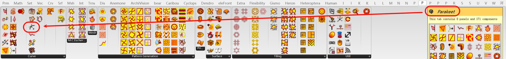
Discontinuity with threshold is of Parakeet.
native discontinuity component find discontinuities by testing level of continuity while Discontinuity with threshold test angles.I really appreciate that Discontinuity with threshold output less points sometimes.
Yes,so there is no doubt that the input curve is planar. I decide to forget all the odd things to save my time.
Your adjustment is inspiring and output better result at the same time.Thanks.
Thanks for your help.
My input is not a surface but one closed planar curve.
Ok, here I extrapolated the surface based on that curve and used that surface to array the pattern. I made the pattern parametric also. Usually I would rationalise the “geometric position of XYZ components” to something smaller, but this way is more illustrative of what’s going on.
This is a much more robust approach because we guarantee a clean input (4 single-segment curves) and everything happens in Surface World.
Right now it just trims the pattern outlines, but you could generate surfaces from the polylines instead and trim those. All sorts of methods are possible.
pattern via surface.gh (36.1 KB)
I really appreciate you modeling logic that You firstly define one regular pattern and then map it on new surface.Thanks.
Nice - good insight.
A thought I entertained but didn’t execute was to use ‘mirror curve’: mirror the two segments (currently in use to derive offsets) using the third segment as the free-form mirror curve. You can use the two mirrored curves with the two original ones to make an untrimmed edge surface and go from there. For this case it should work given the shape of the curves. I’ll see if I can try in a bit.
I take it back - works beautiful in concept, however mirror curve makes the mirrored objects more complex (adds points) while the regular (plane) mirror works better, yet both still produce an open brep* when making the edge surface.
*Rebuilding the curves, as @Tom_Newsom did, can help, though I wasn’t sure that was allowed/wanted. I’d prefer relying on surface mapping as well, it’s more promising/elegant for sure.
Perhaps the only ‘disadvantage’ in Tom’s approach (at the moment) is the edge situation. Profiles along edges of the surface end up open - another layer of robustness will be needed there to close these curves again, not with a line but using the edge segment(s) they intersect. Using Region Intersection can handle this (at a cost, obviously):
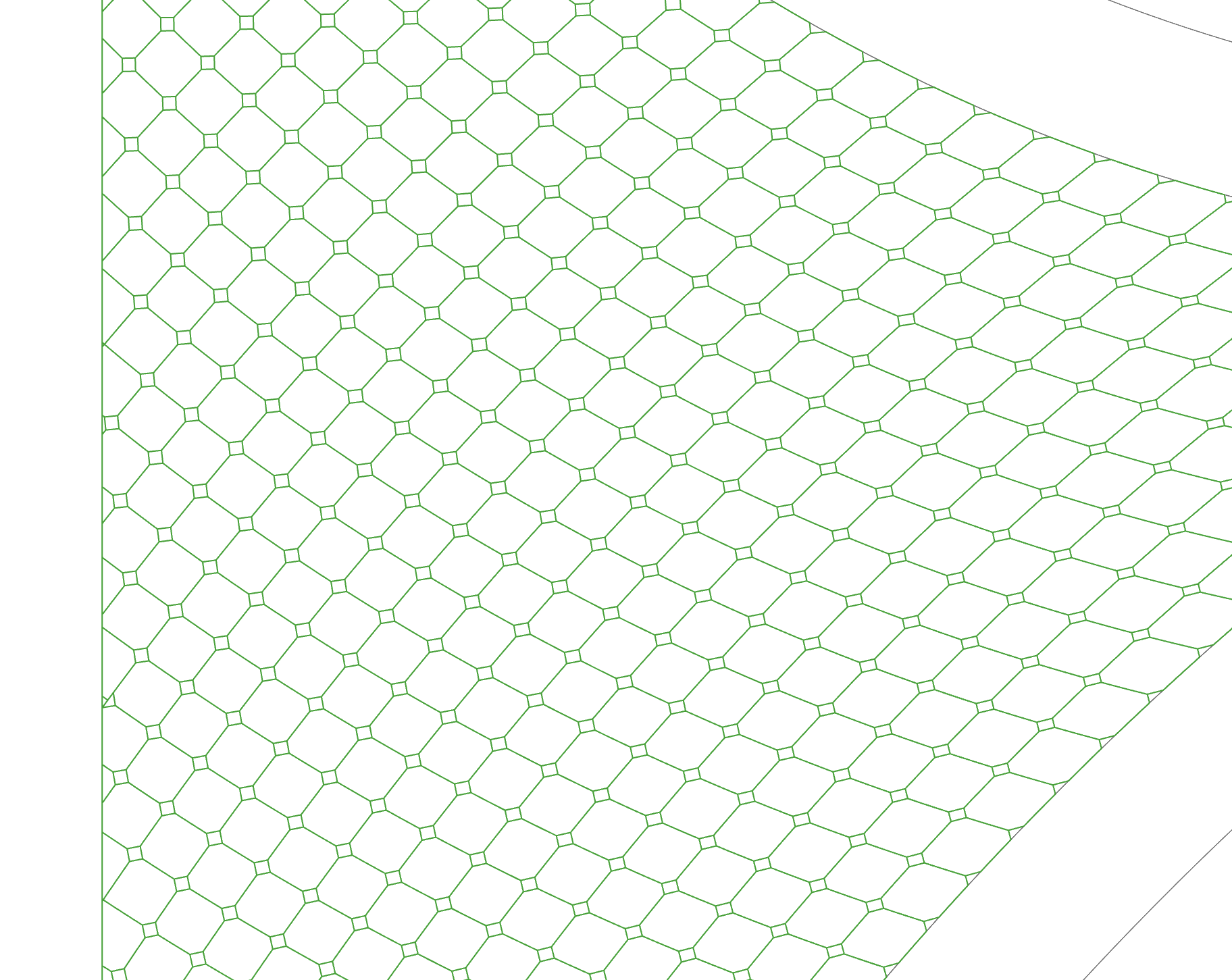
Nice idea.I tried this idea too and the result(blue curves as below) seems more even than Tom’s way.
However,by using the mapping way,it’s hard to control the final result exactly.So I prefer offset the boundary curves directly as we have discussed before.
Thanks for this info,I will try to learn clipper2 plugin in the coming days.
Very interesting seeing the difference in grid spacing. Of course the UV grid varies with boundary curvature. I’m sure there’s a way to “regularise” the UV spacing but if you want exact dimensions then offsets probably are the only way to go about it.