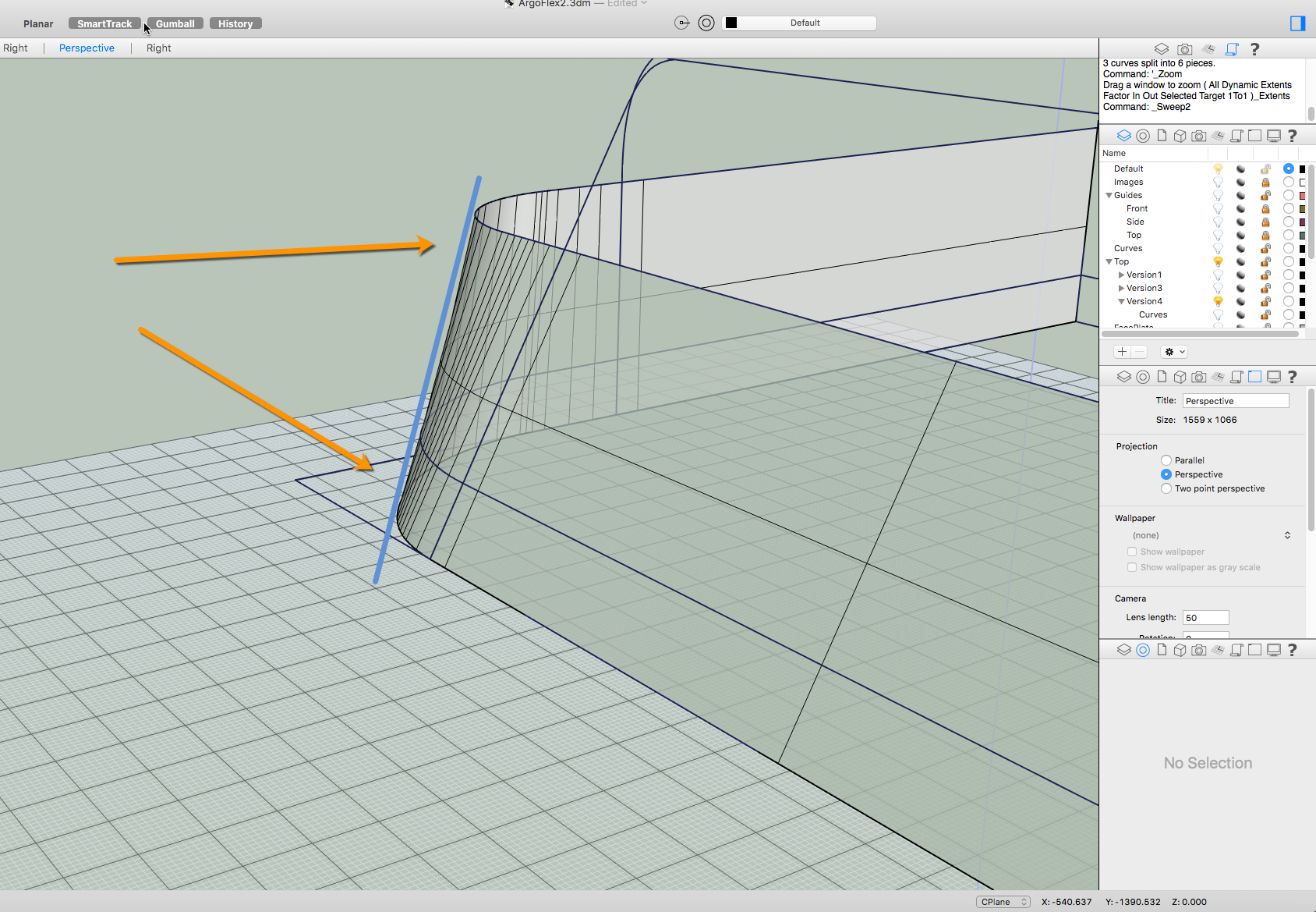
Below is a shot of a 2 rail sweep that included about 3 additional slashes in an attempt to make the surface vertices flat but as I think you can see, the wall around the curves appears to bow inwards. I’m wondering if I’m using the tool correctly or if there’s some technique that would help here.
Hi James - I’d add slashes at the end points of the path arcs that line up and End & Perp on the ones that do not (left side) I’d also leave out the back lines and make the paths open U shapes - the back plane should be just a plane. But, the thing will be much easier and cleaner if you explode the path curves and simply loft across the pairs of curves - arc to arc, line to line…
(Windows, but you’ll get the idea)
Changing the U degree to 5 (Loft with Normal gives a degree 3 surface only) gives a few more control points to help the surface match up at the ends; the neighboring surfaces are also degree 5 in that direction so it is easy to get a clean match - the points line up nicely., Inserting knots at the end helps the surface stick to the lower surface. Note I only matchSrf for Tangency in this example.
Pascal,
Thanks so much for the little vid. It’s worth a thousand texts. I’ve been practicing the method and I went back to the original you sent me. I tried to duplicate your steps but as you can see from the picture, the new line generated does not match yours. Was there some twerking you did when you blended the surface?ArgoFlex2_PG.3dm.zip (12.0 MB)
I probably noodled the controls in BlendCrv a little, yes. BTW, since the end curves also match up nicely (surface edges at the ends are both degree 5, 6 points) the initial surface I made with a loft can be made with EdgeSrf, and the shape will start out closer to the final one rather than be just a straight loft as in the clip.
EdgeSerf - That works very nicely. It even worked with the upper horizontal curve remaining just an arc. I get the idea that matching up curves by degrees is a reliable approach but I still have some issue with continuity. I actually did a matchcrv on all the edges afterwards trying to get the strips to run smoothly. I noticed in the vid that you used the insert knot tool, but I’m not sure what that accomplished. Is that a possible means to true up the edge transitions?
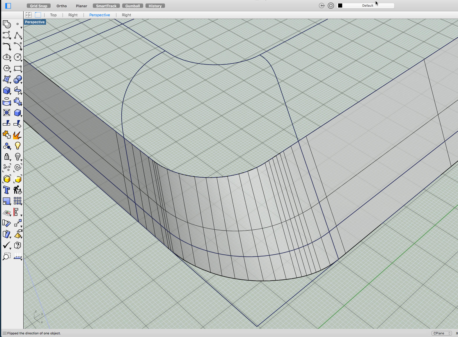
I’ve managed to make things work building from the corners out. There’s now the issue with the top plane and how to blend it into the rest of the surfaces. The top panel was made from the edges of the surfaces created around the perimeter. Is there a cool guy way to finish this off?
Keep in mind that, if I am reading the images right, the base curve on the corner is not a tangent arc as in your original- you do need to decide what you want - if you want G2 continuity, don’t draw tangent arcs and straights and then try to get things G2 and still match up to the arcs and straights.
Here you go. Pascal is correct that the root and midline corner curves are G2, but the top cap curves could be either G1 or G2. The curves were lofted between the root lines and blended curves and the midline lines and blended curves. Those surfaces were then used along with the top cap to create a blended surface G2 at the middle surface edge and G1 at the top cap edge, although you could tweak those settings to your liking. The technique was similar to what I was alluding to on the earlier model, perhaps I will be able to integrate both procedures into one video?
One thing I have noticed with the reference files is that the construction curves are getting off axis by tiny amounts so your resulting geometry that you create is getting racked a bit which causes problems down the line. You might try using the actual measurements as well as the align tool to make sure you’re lining up properly to prevent this. Hope this helps.
That’s the present bane of my modeling. I’m really having a time of it trying to create sound curves. I’ve picked up a few better techniques, but I’m still underwhelmed with my results. The sample you rendered is what I’m aspiring too.
It would be productive if there were some kind of governor that would insist curves remained planar and oriented absolutely to world axis. If you made a video it would be very welcome.
One thing I immediately notice is the use of small planes at the corners rather than one large one that edges on all other surfaces.
That makes for better surface blending?
I placed yours with my latest. I’m getting there! I wonder if there’s an issue with the zebra settings that makes for the the jags.