Need some help with Polar Array geometry

I’m working on a GH script for 3D printing roller bearings. So far I’ve got a working script, but it requires a lot of manual input to get the individual rollers positioned correctly. Here are the rollers for the bearing I’m printing now:

pers%5Bective

Here is a top view that better shows my problem:

top

What I’m stuck on is how to calculate the diameter (or radius) of the polar array and the number of rollers, based on the diameter of an individual roller and the desired tolerance/distance between each roller. Right now I use sliders to control these values plus the number of rollers, and that seems to be working ok, but a proper design should require only the roller diameter and the tolerance value. Or it could be the the overall diameter/radius and the tolerance.

There’s an infinite family of solutions if you allow both the radius of the big circle and the number of rollers to be variable. Basically, for every amount of rollers there is a single radius which works. I think you’ll have to lock down the number of rollers N, the spacing s (which I’m assuming is measured in distance units as the minimal distance between adjacent rollers, rather than angles) and the radius r of each roller. You can then express the radius R of the big circle using those three variables. Would that be ok?

1 Like

Hi Birk,
Does this work for you?
rollers.gh (6.5 KB)

3 Likes

Wowee! Thanks David & Ethan - very helpful replies. I’m going to make appropriate changes to my design and it will be much simpler now.

My first print just ended and it looks like my guess at an appropriate tolerance was too high. The bearing works but is way to sloppy. I’ve also got to tweak some printer settings to reduce stringing. Hopefully next one will be better.

1 Like

If @akilli’s solution works I’ve just wasted a lot of effort :slight_smile:
Ok, my scanner is broken so I’ll just have to talk my way through this.

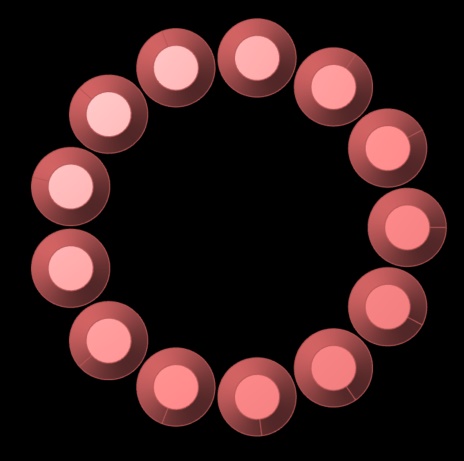
We have the following setup; A big circle with radius R which is the value we’re trying to find. We have N small circles of radius r (which we know) distributed equidistantly along the big circle. Furthermore we want the smallest distance between adjacent small circles to be exactly s, measured on a line connecting their centre-points.

Since the problem is fully symmetrical, we only have to look at 2 adjacent small circles (let’s call them C_0 and C_1, and let’s call their respective centre-points m_0 and m_1, m for “middle”). We can express the distance d between m_0 and m_1 as straight up Pythagoras: d = \sqrt{(m_{1x} - m_{0x})^2 + (m_{1y} - m_{0y})^2}.

So what are the actual coordinates of m_0 and m_1? Well, we can make our lives easier by just pushing m_0 as far towards the right as it will go, putting it at (R,0). Here we are assuming that the big circle is centred on the world origin (0,0). Since N is a given, we also know the coordinates of the first counter-clockwise neighbour C_1. That’s just straight up trig: (R \cdot cos(\alpha), R \cdot sin(\alpha)), where \alpha is the angle between adjacent small circles.

So now we can write d fully in terms of R and N, since \alpha is just \frac{2\pi}{N}. Two times \pi being a full circle, divided equally into N segments. This gives us the lovely equation d = \sqrt{(R - R \cdot cos(\alpha))^2 + (R \cdot sin(\alpha))^2}.

One last piece of the puzzle before we pull the whole thing inside out so we end up with the equation we need. The gap between adjacent circles, is just the distance d between the centre-points minus twice the radius. Right? If we start at m_0 and travel in a straight line to m_1 we first travel inside C_0 for r units, then we cross the gap, and finally we travel inside C_1 also for r units. Thus, d = s + 2r.

We can now combine these two equations so that the whole thing is written as an equality for s:

s = \sqrt{(R - R \cdot cos(\alpha))^2 + (R \cdot sin(\alpha))^2} - 2r

So far so good. It’s not exactly pretty, but it doesn’t go beyond high-school maths either. The big problem of course is that we know s but we don’t know R. So instead of s = something\hspace{1mm}R we need to have an equation that looks like R = something\hspace{1mm}s. This is known as “solve for R” and it’s the difficult bit. Luckily we live in an age of wolframalpha and we can outsource that part of the problem.

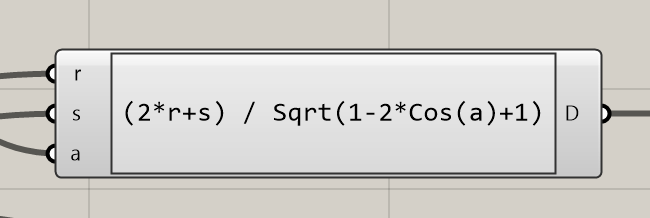
WA thinks that we can rewrite the equation into: R = \frac{2r+s}{\sqrt{sin(\alpha)^2 + cos(\alpha)^2 - 2 cos(\alpha) + 1}}

NOTE: wolframalpha yielded a correct but needlessly complicated answer, see posts below.

Putting that into Grasshopper yields the following: roller spacing.gh (13 KB)

2 Likes

David,
I think our solutions are equivalent - fortunately, or else we are living in different universes. If you continue the algebra in your solution, the sin^2 and cos^2 terms in the denominator ==1, so the result is sqrt(1- 2cos(alpha) +1) = sqrt(2(1-cos(alpha)) = sqrt(4sin^2(alpha/2)) = 2sin(alpha/2)

So finally, your expression is R = (2r+s)/2sin(alpha/2)) This, rearranged slightly, is the same as mine, with your s = my t. and your alpha/2 = my (pi/n)

2 Likes

@akilli, you’re absolutely right, the equation can be simplified to
simplified

Weird, WA is usually pretty good at removing redundancy like this. I wonder if it thought it was working with complex numbers or something. I had a hard time trying to get an answer that didn’t involve i in some way.

Birk,
I’d be interested in seeing the final version. Is this all being printed in one shot?

Yes, it prints as a single object. That’s why the rollers have sloping tops/bottoms.

I incorporated your method above and regenerated the bearing with tighter tolerances. It’s printing right now and should be done in about 2 more hours. If the bearing works I’ll post the GH file and a photo of the bearing, but it might take another tweak or 2 to get it right.

The problem is that the tolerance that is specified is not what actually gets printed, basically because the geometry of the melted plastic loops is different from what is mathematically correct. This happens because the slicer program calculates the amount of extruded plastic assuming it is printed with a rectangular cross section, when in fact it has a more oval cross section due to the melted plastic’s viscosity.

The new version is definitely better, but still has some problems. It looks like I should chamfer or fillet the edges of the inner and outer rings, and the shapes of the rollers needs to be changed too. What happens now is the rollers don’t stay vertical when the bearing turns; this suggests the wide part has to be even wider, and the top & bottom half shafts need to be shorter.

I’ll do those tweaks tomorrow and should have the next result by the afternoon - the part prints in a little over 5 hours.

This is the final version (for now) of my roller bearing GH file. I added fillets to the outside edges of the t rings and tweaked the roller dimensions and tolerance a bit. The print took 5:06 but didn’t function any better than the previous print. I may try making a larger version to see if that helps with the bearing’s operation.

RollerBearing3.gh (30.2 KB)

1 Like

Looks great! I don’t know a lot about 3D printing but could it be the FDM process itself that makes precision difficult?

Yes, that is certainly part of the issue. Building anything out of a freely flowing viscous material means the is simply no way to precisely control the final geometry. Plus melted plastic has a non-zero amount of thermal shrinkage , the effects of which depend on several variables. I’ve had printed parts shrink so much they literally pull themselves off the print bed.

Beyond that there is the issue of adhesion between the multiple loops of printed plastic. The slicing program makes some internal decisions about how to handle this, and even though there are some user available parameters to affect this (like loop overlap, print speed, layer height) it is not something that can be totally controlled.

My sense is that for precise results some method other than FDM is required. HP makes a very fancy/complicated/expensive machine that uses a fine laser beam (or maybe it’s UV light) to fuse powdered material of various types. The results look great, but this is not an approach suitable for individual hobbyists like me.