MESH TOPOLOGY - Edge Length, Face Angles and Vertex Angles

I’m trying to output a list of information about a mesh…

FACE#, EDGE#, EDGE_LENGTH, ANGLE1, ANGLE2, FACE_ANGLE

Where ANGLE1 & 2 are the half angle between the mesh edge and the edges at either end of it and FACE_ANGLE is the half angle between the faces either side of the mesh edge.

It would be good to sort this into common edges but this is not essential.

I can get this info and place it, using tags and dimensions, on the mesh…

But I can’t create the list of info outlined above.

The definition uses Sandbox and Weaverbird.

MESH_ANGLES_LENGTHS_CUTTING_LIST.gh (30.9 KB)

1 Like

That’s very easy with code.Notify if you need a demo (on any Mesh List: BTW Sandbox yields some rather weird stuff [connectivity Trees] if Lists are used - not to mention that makes some out of the 9 possible ones [3*3 = 9 combos]). Using textDots for the information is rather more handy.

See the full 9 Conn Trees from a Mesh List (meaning 2 dimensions per Tree path)

1 Like

Thanks Peter, I’d like to understand how this is done, but I think it could take me a long time to understand how it is done in C#. If you can explain the basic logic behind just, say, FF topology that would be interesting.

I managed to get the output I wanted in the end but I am slightly uneasy about trusting that nothing has been mixed up.

I did wonder if Sandbox was using a different order of faces than the native GH components. It seems to work on my geodesic dome.but I have yet to test it on other mesh structures…

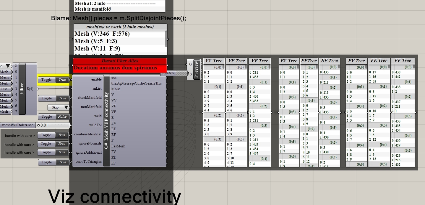
Dihedrals and one dimension connectivity trees (but what if your mesh can being splitted in disjoined pieces? > 2 dimension connectivity trees) :

Given a FF tree: for each branch (path index [path.Indices[0]] is the face index in the Faces List) get the adjacent Faces indices.

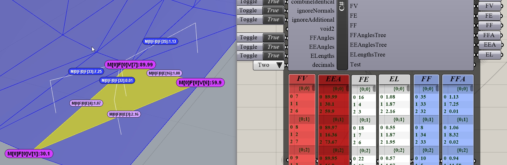
So we have a current Face and the adjacent ones. Thus we have access to the face normals as well (Face normals ARE NOT the mesh normals : aggregate unitized vectors from a given vertex to adjacent vertices).

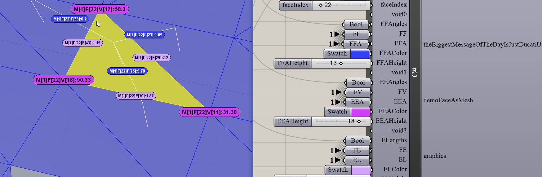
With code for a Mesh M and a Face Index faceIndex this is done as follows:
M.FaceNormals.ComputeFaceNormals();
Vector3d faceNormal = M.FaceNormals.ElementAt(faceIndex);

For a Face pair (currentFace, adjacentFace) find the common edge (List intersections from a FE Tree or take the long way home via a EF tree) and the pair of face normals (currentFN, adjacentFN). Get the edge direction (eDir) and define a plane for the Vector angle calculation.

Compute the cross prooduct (cp) of the currentFN and adjacentFN. Compute the Dot Product (cp, eDir). If is < 0 flip the plane.

Compute the vector angle currentFN, adjacentFN, plane. This is your dihedral (in radians). All these are very easy with code … provided … er … hmm.

Anyway remember that conn Trees relate TopologyVertices (not Vertices) to TopologyEdges to Faces. You can relate TV indexing to V indexing, mind.

BTW: Not sure what Sandbox does since I never use add-ons of any kind (other than Kangaroo). But a Face List is a Face List anyway. I could understand the obvious diference between TopologyVertices and Vertices indexing … but here we are talking Faces.

BTW: For the edge angles there’s a very handy Method (var MTV = M.TopologyVertices;
MTV.SortEdges(); ) that sorts the vertices meaning that you don’t have to bother much when looping on triads of vertices (previous, current, next) and computing the Vector angle (previous - current, next - current, plane (current, previous,next)).

1 Like

When you say “Get adjacent faces” how do you do this? Look at each edge and work out if 2 faces have edges that have the same start and end point? Or is there a smart way of doing this without it taking ages?

Adjacent Faces is what all a FF Tree is about. Sandbox (I assume) can do that.

With code this is elementary (Mesh M, fb the mesh index in a mesh List):

var MF = M.Faces;
for(int i = 0; i < MF.Count; i++){
MeshFace meshface = MF.GetFace(i); // not required for a FFTree, mind
int[] neighborFaces = MF.AdjacentFaces(i);
FFTree.AddRange(neighborFaces, new GH_Path(fb, i));
}

In general a Mesh (and a Brep) is a mini DataBase where TopologyVertices, Topology Edges and Faces are connected via their indices in the 3 Lists [TV,TE,F]. What is connected with what is available directly with Methods like the one exposed above (well … directly … for the 7 out of the 9 possible connectivity trees anyway [for the remaining 2 one needs a few lines of code]). Any add-on thingy takes advantage of these (Rhino SDK) and does what it does.

BTW: These 6 Trees are what you are after (all Faces related connectivity [FV,FE,FF) plus Face dihedrals [FFAngles], Edge to Edge angles [EEAngles] and Edge lengths [ELenghts]. Spot the 2 dimension connectivity even for a single Mesh (that is splitted in disjoined pieces and thus … we have actually a Mesh List).

That said understanding these connectivity ominous things is critical. Let’s focus on a FV Tree for Mesh 0 [path.Indices[0]] and Face 0 [path.Indices[1]] : The 3 indices listed are the TopologyVertices indices related with that face. So for, say, the current index 7 the previous is 6 [wrap] and the next 1, So we get a current vertex and a previous vertex and a next vertex. So we have an angle from vectors (previous-current, next-current) and we put that into the EEAngles Tree (degrees). That’s the correct way where vertices correspond 1:1 to edge angles and everybody is happy (well … I do hope). Same logic for dihedral angles (Feces 35, 33, 32 adjacent to Face 0) etc etc.

1 Like

Right, so this info is actually in the mesh object. It’s not just a list of faces, vertices and normals that you get out from the DeconstructMesh component, there is actually more info there defining how it is all connected together.

And this is why non-manifold meshes are bad… the connectivity database has nulls in it?

And I’m guessing that Mesh Weld and Join components are checking this database and fixing it where possible?

Thanks for the lesson!

Indeed as I said the Mesh (but the Brep as well) is not just info about TV, TE and Faces (the terminology is different in Breps [minus the Topology thingy] but the concept is the same: stuff connected, that is, via their indices in the 3 main Lists of things that compose a Mesh (or Brep)).

Non Manifold on the other hand (see Rhino SDK on that matter) is another animal. In general avoid doing buisiness with these.There’s Methods for checking if a Mesh is Manifold and/or Valid.

Exactly how the Weld algo works I don’t know (but I can guess the Join approach).

Anyway the angles and edge lengths things that you are after are widely used in AEC where we need to address clash issues (in truss members and the likes) AND envelope clash issues (that’s why the dihedrals are critical). Clash is always computed via trigonometry AND NOT bool ops (for obvious reasons). We don’t display all the info mind: only areas where, say, an edge/edge angle is too small for some MERO sleeve or bolt or cat or dog.

But we do display individually stuff like yours on a per Mesh Face basis just for inspection. Text Dots are rather the norm for that (see the string of info, not just a value but what mesh index, what face index, what other index etc etc):

Of course multi queries are also possible: show me all the EEAngles that are smaller than this vallue or all dihedrals that … blah, blah. Correcting live a Mesh/Brep subject to clash issues is another animal and 100% impossible with components.

Quick question if you are still following this thread…

When calculating dihedral angles between faces it is important that the Mesh normals are pointing in the right direction which can be solved by unify mesh normals etc. What do you do with a Brep? I.e. how do you get the face normals of a Brep and ensure they are all pointing inwards or outwards?

I used the Planar component to give me the plane of each face as I am working with polyhedrons and then just used Deconstruct Plane to give me the Z vector of those planes. Unfortunately this doesn’t always give a direction that points outwards.

If testing with a Normal length of the distance to the center, then one can test if the vector end point is inside or outside the polyhedron (or box, etc). If so, then flip.

// Rolf

If the face normal exists in the brep object it should be possible to just reference the normal rather than calculate it or get it from components.

But I see your point. Thanks for the reply!

Perhaps I didn’t understand your problem, but I’ve had (solid) boxes with one surface normal unexpectedly pointing “inward”, and so I had to find out which one so as to flip it. I thought you had a similar problem.

// Rolf

If the Brep is closed then normals point outwards. If not you need some logic to define what is “inwards” .

On the other hand as I said Sort vertices clockwise … but … wait … that’s for meshes (and TV) ,

On the other (other) hand … for something that can being represended with meshes … blah, blah.

Obviously Dot,Cross et all are your main arsenal but the issue is against what. Notify if you need a small demo.

BTW: If the Brep is not “ordinary” (kinda like a freaky thing made with TSplines etc) then testing against some center of mass is not recommended at all.

BTW: Here’s an unfinished thing for the brave (don’t bother about how it works … just puzzle yourself with the normals stuff) :

Brep_normals_V1.3dm (52.9 KB)
Brep_normals_V1.gh (125.5 KB)

  1. Mesh Faces from a Mesh are randomly taken (and sampled into a new Mesh).
  2. A Brep List is made from each Face taken.
  3. Breps from 2 are joined yielding a chaos of open breps that may (or may not) being randomly flipped (life sucks). Flip does inside out stuff with regard normals.

The 1Z question: what about the normals ?

All good Rolf, you did actually help me out because I realised I could use EvaluateSurface to get the face normals which gave me normals that were all pointing outwards. I had used the Planar component which gave me face surface planes but some were pointing inwards.

Thanks Peter,

That seems to flip normals randomly, but how can you get a list of Normals (from a Brep or a mesh) for each face? Can you just output a normal for each face index? I.e. is that data stored within the Mesh or Brep object?

It flips randomly (if user wants so) the Breps derived from the join Method. Meaning that the normals are flipped as well. However if the percentageSkip == 0 then a solid Brep is made (if the donor mesh is solid) and … the orientation is the classic outward (reported anyway in the 2nd part). That said the brep orientation (inward,outward, undefined and not solid) is available only if the Brep is solid (obviously) otherwise not solid is reported.

See attached where the 2nd part is supplied (minus the checks for the normals).

Brep_normals_V1A.3dm (120.2 KB)
Brep_normals_V1A.gh (120.8 KB)

If the output is Brep then centers and normals are according the BrepFace enoumeration (main dimension in the Trees). If is Mesh then the MeshFace enoumeration is used.

Anyway see the demo n2 where a hole is present and that … makes things impossible with regard testing (Dot,Cross etc) using something the likes of CoM etc etc.

But what is outward or inward is one thing: the big thingy is a policy to measure the vector angle with regard the right plane (some answers above I’ve explained a way to do it).

On the other hand if your stuff is always convex (+ no holes) then checking (via Dot) using a face centPoint and a bounding box is rather handy [checkVector = ptOnBoxClosestToCent - centPoint, if Dot(normal, checkVector)<0 flip the normal]

But since checks are countless (and rather - more or less - case specific) it could be good if you can provide a “typical” topology (or a range) that you are after. Especially if open Breps are required (envelopes, roofs, facades and the likes).

BTW:

Given a centPoint (per Face), a normal and a checkPoint and the checkVector: checkPoint - centPoint and the DotProduct here’s some ways to cut the mustard (indicative, mind).

  1. If the brep is closed … why bother talking?
  2. If is open and sheet like and “flatish” you can use a plane fit to centPoints and the plane.ZAxis as the checkVector. Works when it works mind.
  3. If is open and not sheet like and the topology is “cooperative” you can fit a Sphere to the sum of centPoints (an engulfing one) and define the checkPoint as the closest to centPoint (or the Sphere center). Works when … blah, blah.
  4. If is open and freaky you can use some user defined direction (or many) as the checkVector. Maybe using the sum of unitized normals as well. Works when …blah, blah.
  5. If nothing works (Karma, what else ?) and the topology is “kinda” the one exposed in the attached demo you can use connectivity and other freaky things to test normals from this brep faces to other brep faces. That’s a bit complex to explain here in detail. Works when … blah, blah.

Plan Z: Wait until AI hits the masses and be a happy bunny (most unlikely … but anyway)

OK, this is all good BUT… do you have to calculate the angles between the faces or is there some tree / database table of these angles similar to FF, FE etc that can be referenced directly? I’m guessing not for Breps but maybe for meshes?

As I said many times there’s connectivity stuff for Breps exactly as for Meshes. Vertices, Edges and BrepFaces yield 9 possible combos (VV,VE, VF … FV,FE,FF).

I could very easily add a 3rd thingy in the demo provided that could do the dihedrals calculation on Brep Lists … but you are after solutions based on native components whilst I’m on the far far opposite side of things.

Anyway, try Sandbox that does (I assume) some of them.

1 Like