Hi,
V5
sweep1 ,
how do I stop it dipping down then up to next profile ?
and the sharp creases ?

lumpy sweep1.3dm (338.8 KB)
Cheers
Steve
Hi,
V5
sweep1 ,
how do I stop it dipping down then up to next profile ?
and the sharp creases ?
lumpy sweep1.3dm (338.8 KB)
Cheers
Steve
Hi Steve, it’s likely the quality of the curves you’re using for your sweep, how many control points do they have? You want to make sure there are as few as possible. I’m looking at the model now but can’t find the curves in the layers.
Do you need those additional sweep cross sections? If you rebuild the sweep curves and only use three - the ends and middle curve it’s not lumpy. Based on the curves you have now the lumpy shape is what’s needed to create the swept surface
Hi,
I have taken the highest profile, and done a sweep1 to the lowest two, I get the smooth transition.
However there are creases along the edge, yet the progile is based on a circle.
In blue the method of making,
two circles, a line tan tan, a vert line to quad, a trim line to larger circle quad, then trim and join.
end profiles,….reduce height of the top circle in the profile, keeping the other circle same , make line tan tan circle again.
sweep1 to rail.
How can such circles generate these sharp creases ?
lumpy sweep1 now 3profile sweep1 creases.3dm (240.5 KB)
Cheers
Steve
I would use different profile curves with degree 4 to eliminate the knots that break the curvature of the current curves.
If you try the “Loft” tool you will realize that it produces far smoother result, but using the current curves will force you to rebuild the output, thus gain some unwanted deviation. Just don’t use 0,003 , because for some reason that will cause some BUG with the geometry… ![]()
@Steve1 It’s due to your profile curves–as @Rhino_Bulgaria said, there are knots in them. See these points in the profile curve, they will be problematic. If I simply extrude that curve to create a surface you’ll see the discontinuity. Steve the way you described creating these curves yes you’d think you’d be okay, but it’s not, it added these extra points, I’m tagging @theoutside Kyle since he’s excellent at explaining these things.
Kyle check out this thread it’s good fodder for a learning YouTube tutorial
Hi,
my naive trusting brain, that of a newbie though been at this 10 yrs or so since V4
assumes, a circle made with a cirle tool, and another, ditto, , and a line tan tan both, and another from quad. would be as pure as the driven snow, and be good for a sweep.
having to fiddle with it and so on, hells bells no.
so is there a fundamental bug or weakness ?
Would Solidworks or another prog create the same creases with the same simple profile creation ?
I find this worrying/disturbing etc.
Rhino is as it is, responsible for evening meals hours past when they should be. and an unhealthy PC duration night after night.
00:24 and exiting PC due to Rhino.
Steve
Thank you for taking the time to respond and teach!
@Rhino_Bulgaria
Hi,
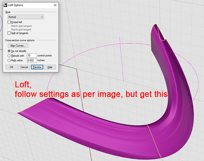
tried for _Loft, select the three profiles, as I only had three anyway, place your settings in the box, and get this.
I try for rebuild degree 4 the largest profile, and the vertical line gets bent.
it needs to be vertical, not sure how improving it means losing a straight line.
I just dont understand why a pure looking shape made of two lines and a circle is BAD BAD BAD as far as profiles go. Its the most unsettling thing to discover for me since I started out with Rhino 4.
How can a circle be bad.or even a line. I feel sick !
Steve
The “Loft” tool tries to interpolate the shape along the input profile curves. Think of it as an elastic rod that you bend along hard points. Since you use just 3 profile curves, the interpolation of the shape is accelerated mostly at the middle one, whereas each tip is almost straight. If you use 5 profile curves instead of 3, that will give more definition for the “Loft” tool to create the desired shape.
Hi,
whilst I know the shape of the three profiles, I dont know the shape of the other two.
So not sure how I could use Loft for such situations.
I am somewhat perplexed, upset, bamboozlled etc etc, with the fact that a circle is NOT good for profiles. I feeel like the carpet has been taken from under my feet.
How many other users are unaware of such.
I will put such up as a separate thread as it warrants one !
Steve
Circles are ok. Just make them degree 5, as you would with their best friends, the arcs and the cylinders ; )
The best way is to not use sweep.
First of all don’t let anyone tell you those are poor quality curves.
Rhino’s sweeps and lofts should be able to recognize that all the lines should be organized together in the final surface and all the arcs go together also. But Rhino’s algorthm tries to mix parts of the lines with parts of the arcs and it all becomes a mess.
When you get rid of the knots as others have suggest you lose all the accuracy and quality of the profile curves.
So if you need accuracy and you recognize that the lines define two sets of surfaces and
Don’t_use_sweep.3dm (271.8 KB)
you can make the arc surfaces using filletsrf
Here’s another approach, treating the surface as two parts split along the crown and using sweep2:
To get the new rail along the crown, in the right view create a straight line the same length as your existing rail and use flow along curve to flow the profiles along it. Then create a plane placed through the quads at the crown of the curves as seen in the front view. Put a point at each intersection of a profile curve with the plane and draw a curve (arch) through the points. Hide the points you used.
Turn on control points for the new arch curve, then turn on the curvature graph and micro-adjust the control points (symmetrical about the middle profile) in the x direction in the top view to get a smooth curve. When you are happy with the curve, scale each of the profiles in the x direction from their max x end so that the peak quad is back on the curve.
Once all the profiles meet the curve, delete the original profiles around the disk. Then flow the new ones plus the new arch curve back onto the original rail, using the straight line as the base curve.
Create a new outer rail as an arc passing through the outer ends of the new profiles and centred on the disk axis. Create a new inner rail using curve through points on the inner ends of the profiles (these don’t lie on a circular arc). Split the profile curves using the arch curve.
Use sweep2 with the outer rail and the arch rail and the outer profile sections to create the first surface part. Use sweep2 with the inner rail and the arch rail and the inner profile sections to create the second surface part. Join the two surfaces.
Cleaning up the profiles so they align well was important in this. Yours were pretty close, but not quite there. Introducing a rail through the crowns, presented on a flat plane, makes it easier to see how your surface will flow.
lumpy sweep1 but not lumpy sweep2.3dm (628.6 KB)
HTH
Jeremy
Funny visual bug in Rhino 7. Here is the same file posted by @jeremy5 , except that the view is matching the one in my video. I have seen this bug so many times. Happens only on custom display modes with supposedly hidden isocurves, such like Bobi X14 etc.
lumpy sweep1 but not lumpy sweep2 (Visual bug).3dm (691.9 KB)
Bobi X14 for Rhino 7:
Bobi X14.ini (13.9 KB)
Bobi X14 for Rhino 8:
Bobi X14 adjusted.ini (15.4 KB)
Environment map:
Crackdown 1.rar (54.6 KB)