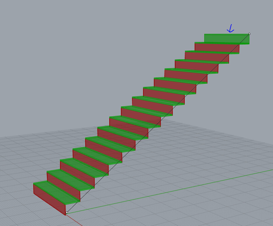
Hello, I am working on one of the ThinkParametric lessons and am trying to build it into a more practical use problem. In this lesson we build a staircase along a user defined curve with variable stair count input.
My modifications have been to change the extruded steps into surfaces with thickness. I have split the lists into 2 lists by item index to separate out the risers from the treads. My first problem is the first item of the list is the top riser. The second is the bottom riser and alternates from there moving upwards, between risers and treads. This places the top most riser in the list with the treads. Why is it listing it this way?
When I extruded each riser/tread, I chose the XZ or XY plane for the direction. How do I choose a normal vector to the extrusion or surface in place of the XZ or XY plane? (Same for the unit z vector?) It works as drawn if the stairs stay in this orientation. If I rotate the stairs, then the stairs.3dm (77.4 KB)
XZ plane will not be correct anymore.
stairs 2.gh (25.0 KB) stairs.3dm (77.4 KB)
Thank you for any help. I am new with GH so any suggestions on how to make this a better model or more efficient, please let me know.
Thank you
Kevin
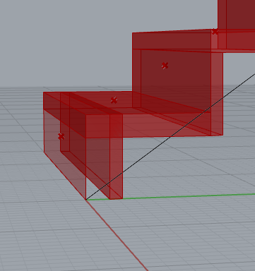
I came up with a partial solution which causes issues with the top and bottom riser. Top issue is still with the order of the list. Bottom I am not sure what it is from. I know there are always many ways to solve a problem. What would a better way of doing this be?
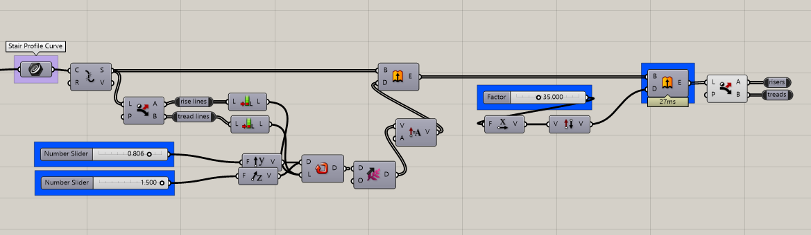
Sorry I forgot you were asking this - I meant to answer: the original polyline has its segments in the correct order from your point construction. However, once you extrude the polyline and then explode it into rise and tread surfaces grasshopper forgets the order of the segments. Why? Just because, I guess, as they’re no longer the same thing (I am sure there’s a more ‘computationally-appropriate’ reason but I don’t know it). Hence by using the segments to extrude your surfaces (separately) the order of the segments is inherited.
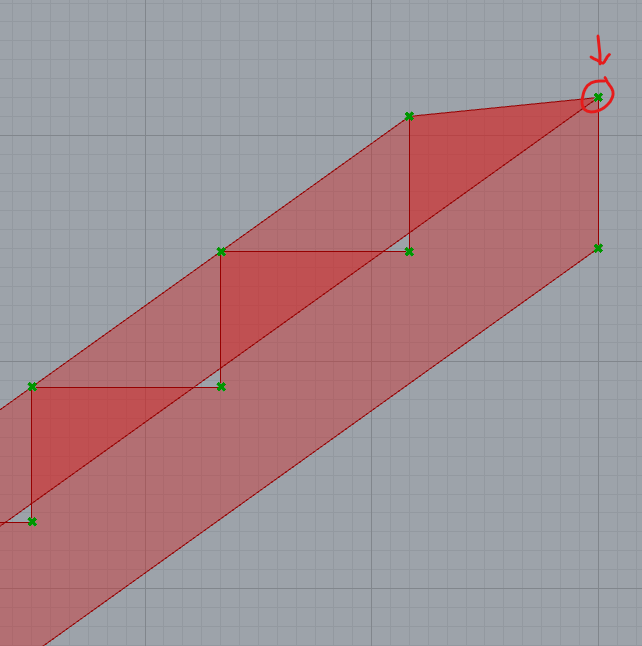
If you must continue with exploding your original polyline extrusion then you have to sort the surfaces to re-obtain your order (and also reverse the risers’ surface normals): stairs 3b.gh (30.7 KB)
And you almost had it in your original file, you just needed the actual UV coordinate for the surface (but this does nothing about the list order problem):
Stairs (without landings) are relatively simple, yet the wording of your first post and GH file are complex, so it’s more difficult to reply than you might think.
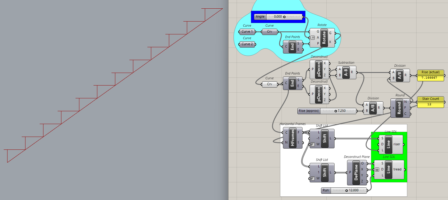
Stair count is usually determined by the difference between one floor and the next. Given a line, it’s calculated by the difference in Z between end points. The Z difference is divided by slider ‘Rise (approx)’ value and then rounded to get ‘Stair Count’. Then Z difference is divided by ‘Stair Count’ to get 'Rise (actual)'. Like this:
Note the ‘Angle’ slider (blue group) that rotates the stair guide line ±180 degrees.
Instead of lines we could create surfaces, extrude them and “Bob’s your uncle” as the saying goes. To be continued… Hope this is helpful, it’s easier for me to show how I would do it than to answer questions about a lesson I haven’t seen and have no need for.
I saw a shortcut and took it. Used domain boxes instead of extruded surfaces. And just noticed that the stairs need to be lowered by the tread thickness… What was your question again?
Details of stairs How many stringers have been discarded because a carpenter got confused?
All this code from the orange group and below it is for the stringers The purple group moves two copies of the centered stringer from the orange group.
Thank you @René_Corella , @Joseph_Oster , and @leopoldomonzani . I am trying to digest all of your solutions and have learned quite a lot from each method. This is all overwhelming at the start but it is slowly making sense. I appreciate your time in helping explain how you would solve this problem.
@Joseph_Oster in my 30+ years in the building trade, I have seen a few stringers thrown away . Not that I ever had that problem. Your solution is the process on how I would build this in the field. One question about your example, on the stringer, the top most point used is the end of the original curve. Because of this the top tread cut is not parallel to the tread surface (back point of the tread needs to be dropped the thickness of the tread. I have been searching through the diagram but am not sure how to isolate this point. My guess is it needs to be done before the entwine component.
The tread is correct, the error is in the stringer. To fix it, I added the highlighted Move(orange group) to move that top end point down for the stringer. Good eye!
The Replace component is operating at the other end (bottom / start) of the guide curve, which I assume touches the finished floor at bottom and top levels.
I have built some deck stairs similar to those in the past. 30" run 7.5" rise. I would frame it differently but could use it in a rendering to show clients.