Oh boy, you are right! Struggling with this, too. ArchiCAD is cool, but how come such a highly developed software can be brought to it’s knees by importing some stupid mesh with a polycount every cellphone is comfortable with…
You mean Attribute User Text? Create key/value pairs to your liking.

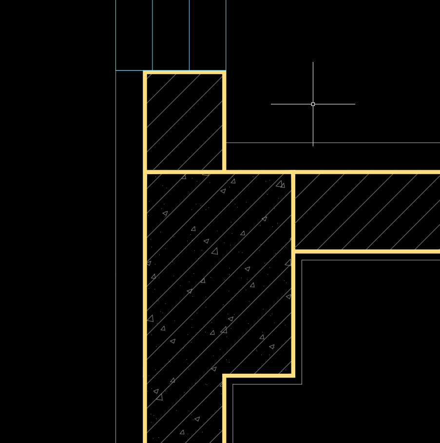
VisualArq brings ‘real’ custom parameters, though:

Please include the colors of the section, too! Really.
But wait! I sniff a chance here to really boost Rhino’s drafting capabilities…
A proposal:
Why not generalize ‘Section Styles’ to ‘Styles’? These ‘Styles’ would be applicable to objects or layers, and would contain all the usual parameters for an object’s appearance:
Display Color, Display Mode, Material, Linetype, Linetype Scale, Print Color, Print Width, Clip, Section Pattern, Section Pattern Rotation, Section Pattern Scale, S.P. foreground color(!), S.P. background color(!).
You mentioned a Section Style Manager (btw. the link is private). Make it a Style Manager, where a list of styles can be defined.
Every object parameter would then have an additional value ‘By Style’, so it can either follow a style or have a local override.
The great advantage of this would obviously be to have a central hub to change many object’s params at once.
Some time ago I uttered the wish for global colors. These ‘Styles’ I just mentioned would deliver global colors as a by-product!
To take this even further, Layouts/Details could have this Style parameter, too, to globally override what’s shown. This would make things possible we know from the ‘big’ architectural apps like ArchiCAD, Revit etc.
Think about it: there’s a Style defined, maybe ‘shop drawing 1:500’, where you define the complete looks of what goes to paper (or DWG output, please). Change maybe a color or a linestyle in the Style Manager, and pling!, the complete drawing changes. Pretty much what Display Styles already do for the viewport appearance, but for print.
Not that I have thought this through fully (how could I), but doesn’t this sound tempting…
Thanks!