Kuka & English wheel paths from doubly curved surface:

Good looks (on the limit of acceptable), tractor motor (is so wrong that H/D does a rich mixture for the back cylinder as an attempt to cool it): A cafe “racer” kinda my BMW R1200S (100% crap, but if you want to buy it > hurry> lot’s of pointless extras > don’t miss that opportunity > call day/nigh with cash on hand).

V1B preview: I’ll include a variety of checks in order to test an input thingy that looks OK … but is not. Kinda “extending” this (case: not Surface):


That said, since V1A accepts BrepFaces (holes, trims etc) it does the U/V division using the underying Surface … and this may mean business in a variety of ways (assuming that the Surface is not crap). For instance imagine a quad edges BrepFace (no trims) derived from a very big Surface and another looking exactly the same but done with a Sweep2 using the 4 edges … blah, blah. I think that R6 SDK offers a handy Method for some cases “like” these (shrink if memory serves well).

That said in 99.99% of real-life cases issues occur because the user wants to believe that his stuff is OK. So the “ideal” C# should be 10% code and 90% checks that do this (or that) for locating what’s going wrong. Very boring I confess (but life sucks).

But soon all that would become history: advances in 3dPrinting etc etc (USAF is using load bearing parts done that way long time ago and rumor is that AMG does some tricks in Lewis F1 engine that are rather sci-fi … etc etc).

Funny you said that… that’s exactly how it was created. Not by myself but by someone else. Is there a work around where I could recreate the surface properly?

I wasn’t even aware of this issue… it make perfect sense now thinking about it. I’ve simply never had to worry about doubly curved surfaces in the physical world until now.

Okay we’re getting close! After a lot of research I was able to combine a grasshopper def with a c# to create the Gaussian curvature, recursive subdivisions and their principle directions all in one. I need to modify the c# so that the subdivisions change in size based on the Gaussian curvature being positive, negative or zero.

Osculating Circles_Vectors & Recursive Subdivision (C#).gh (11.6 KB)


Double Curve Test.3dm (282.0 KB)

Your issue Numero Uno is that you don’t use the V1A (the thing that deals with BrepFaces instead of Surfaces). This means that you are into a big rabbit hole with many entries but not a single exit (like tuning a Harley Davidson). Since these days the majority of facade panels are not Surfaces (unlike stuff the likes of Bilbao) … well … blah, blah, What if you receive a part that looks like a triangle BUT may be a trimmed thingy OR a Surface with a singularity OR a piece from outer space? What if you buy a V4R and set the engine mode to R? (and disable TC).

Other than that you’ll also need a filtering policy (like in V1A). Other than that you’ll need a proper recursion. Recursion is explained in depth in the Prophetic Trilogy:

Screen Shot 094

With regard some “diagnostics” related with a BrepFace that is not a Surface:

  1. You can report the areas (Face, Underlying Surface) and if they differ beyond an user defined value … do something.
  2. You can count the pieces that make the edges, say in a thing that looks like an OK quad Surface (but is a BrepFace). If an edge has 2 pieces and the corresponding one 66 … blah, blah.
  3. You can play with Locus points on the edges (that’s a bit tricky).
  4. etc etc

BTW: With regard your recursion (up to tol). Imagine dividing a thing, picking a search policy (say min OscR in U or V as shown below), getting the points where Gaussian > tol (you can control that value obviously … but avoid getting lost in the translation) … and defining an Interval of interest (say the upper 30% as shown). Depending on the U/V values (the resolution, that is) we get either this:

Or that (or any other):

Notice that the percentage is the same (obviously) and the search Interval bounds are almost the same (in real-life are the same)… but you get a more refined result. Plus the u/v enumeration is grid like (meaning easier LINQ queries for the final part of the story)

Given all that the 1M question is: why bother with recursion?

And why bother with flat spots? (Gaussian < tol). But we should bother with the GC sign (meaning green TextDots for + , red for - … that does the VIB as well).

BTW: Your recursion is not correct: can you see from that pic why? Well … because you test for planarity 2 corners (so the blue and light blue ones stay intact) instead of doing the right thing for testing a quad planarity: min diagonal distance < planarityTol … or … wait … is better to use the R Method for that matter, case: bulges with planar corner pts etc etc (I’ll fix that by introducing the classic History Tree as well).

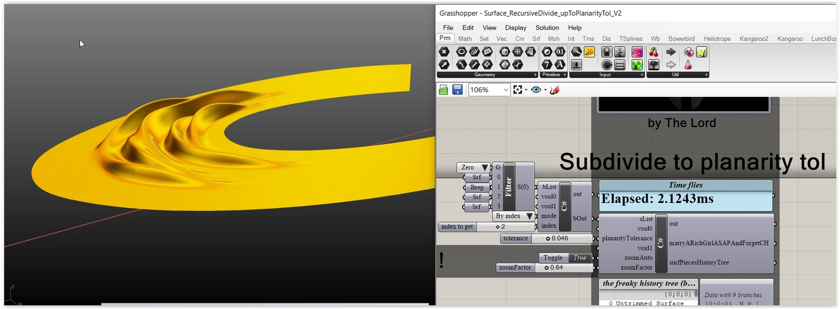
Prior the history (and some other freaky things) here’s your recursion (kinda a Pani V2: Less is waaaaaaaaaay more):

And here’s the correct results:


Get the thing (prior the History tree):

Surface_RecursiveDivide_upToPlanarityTol_V1A.gh (76.1 KB)

BTW: What are you going to do with a Surface with a singularity? What are you going to do if your father in law offers you a KTM RC8R? Or the widow maker? (ZX10R) Or the other widow maker? (Honda CR500).

Yep, James here from Zahner :slight_smile:

Looks like you have been busy over the weekend. From what I can tell you’re on the “right track” or at least a similar track as I went down. (Using osculating circles to determine principal curvature then linking minimums together to determine path direction.)

A key assumption in our early work was that “more shape” required denser paths- to accomplish this we recursively sampled areas with tight curvature to generate more sample points. Since Elena’s work I’ve pivoted away from this a bit and now adjust pressure to achieve additional shape. In either case, once we had our 3d tool path we remapped it to the flat stock and programmed the kuka as an External Tool which makes the robot programming straightforward.

As far as material properties - temp I don’t see as being an issue. I was speaking more toward what material and thickness you choose. In a single sheet you’ll see thicker and thinner areas (mill tolerance) - so forming strategies should take that into consideration. With stainless steel work hardening happens quickly if you have too dense of a path - aluminum is more forgiving but proposes other interesting challenges.

Variables to keep in mind:

Path
Path density
Wheel Pressure (adding a coordinated motor here is on my todo list)
Angle of attack at the wheel
Wheel crown
Tensioning on the robot side (relates to angle of attack, pulling downward)
Exiting pressure (force placed on the sheet as it exists the wheel)

Lots to think about!

2 Likes

Peter,

As always, thank you! I’m struggling to keep up.

So whats actually changing is the size of squares based on the diag length sum but what about the color? Is that just to differentiate from the adjacent squares?
I’m leaving surface with a singularity alone…

This is great information you’re giving. I’m learning so much from all of this!

Matrix reloaded:

  1. A Quad Surface (during the recursion) is NOT a quad Mesh Face: this means that on first sight you may think that a diagonal min distance check is the thing to do … but think a bulge > meaning that the first is the good thing and the second the bad/naive thing:


  1. IF you base your stuff on the recursion (As I said, I can hardy see the point) you don’t need colors … because the smaller the pieces (or the more dense the u/v space mapping - see images with white dots below) … blah, blah.
  2. Imagine a resursive subdivision where the loops (L) are obviously topology related and thus unpredictable. Imagine a 3 dim tree where the 1st dim is the donor surf index (SI), the 2nd the state of L and the 3rd is either 0 meaning candidate pieces or 1 meaning planar ones. If you store each step we have a history Tree that starts from a branch (SI;0;0) … has L-2 branches (SI;state; 0), (SI;state;1) and ends in a branch (SI; L; 1) - meaning that all the pieces are declared planar. This is the proper way to do the job because it allows you to test each recursion loop on a per loop basis.

Results on some LOL test Surface (exploiting the last history branch):


Me? I prefer this way (seach via an Interval):

Than that way:

BTW: If you insist on Colors (but why?);

Surface_RecursiveDivide_upToPlanarityTol_ColorDemo_V1A.gh (483.1 KB)

Peter,

Ahh now it makes sense!

Either way is fine with me as long as it accomplished what I’m trying to accomplish. Visually it would be there just so others can see what the surface is doing. That’s all. But I agree. It’s risky to assume a surface is proper and Brep is the way to go.

I haven’t been able to use the V1A because for whatever reason it never works for me.
Capture

The end goal, of course, is to understand what a surface is doing in order to extract the principal curvature and then link the minimums together to determine a path direction. The path essentially runs perpendicular to the desired curvature.

I will keep trying to get your defs. Thanks for all the help!

James,

We’ve been very busy! I’m learning more than I ever thought I could about something I thought I understood.

I assumed the same thing. More shape = more path. That saved me some time. Thank you for this!

And this will help a lot in the near future! And adding a coordinated motor to the wheel pressure? Very smart!

Thanks for all of this info James. This saves me weeks!

Well … you had a Harley > 1st degree crime > now is pay time (no mercy).

BTW: pack in R5 format and post the stuff that you are using with V1A - the more cases the better (include bananas as well for testing the ready V1B).

BTW: For V1A I mean this (not the recursion related V1A thingy):


Get this as well

Surface_RecursiveDivide_upToPlanarityTol_ColorDemo_V1B.gh (484.4 KB) .

Update: Completely new BrepFaces stuff under way, using some strictly internal things [a few and slightly castrated to be honest] : 3 times faster, 5 filtering modes (4*Osc R’s, Gaussian or Mean) , 3 visual modes (2 color dots, 2 div pts colors, U/V mapping), no recursion (just filtering according U/V div resolution).

2 Likes

Peter,

It’s been a busy week. Oh I see I had the wrong def. Okay I’ll check this out soon and upload some things.

What motorcycle collection do you have?

Various Ducatis (divine but utterly unreliable) plus a Blade (perfect but kitsch), a RC8R (stunning looks wrong anything else) and a R1200S (crap). Plus various dirt bikes … and the official widow maker (CR500).

Testing some queries on partial results (within a given search range):

That said - case recursion - since the thing alters the enumeration you’ll need U/V mapping coordinates in order to sort things.

BTW:

Surface_WhatIsCurvature_V1.gh (119.7 KB)

Peter,

Those tests look great! Now if I could only figure that out.

That’s a pretty large collection you have there. I saw some of your other work on the web somewhere. Do you design motorcycle parts?

Basically for fun … and some times for some friends who operate in the custom market sector [related solely with superbikes]. I do powerboat stuff as well pretty much for the same reasons.

1 Like

Hi Seth
I know this is old and wondered if you achieved what you needed but in practical terms I suspect not. I can see that your input is far from simple but from what I can see you are way over simplifying the methods needed to achieve complex shapes. I have lots of experience from a practical point and can make almost any shape but it’s not all done on an English wheel. Even with very tolerant materials such as certain grades of aluminium, shapes can not be achieved without inter annealing processes or more importantly shrinking processes which are not done on a wheel. This is because a wheel will induce far more work hardening of the material than say a stretch forming or press process for the same final shape. A small amount of shrinking around the perimeter will produce quite a lot of shape and will negate a huge amount of stretch, thinning and work with a wheeling machine. I can see how you might think that wheeling up will Theoretically eventually achieve the the same shape but in practice it will not. So it comes down to what shape you are trying to produce. I would say if it’s quite a low crown of fairly spherical in nature you will manage. If it’s High crown, more complex or contain reverse curves you will not.
The bigger the piece of material the harder the extremities are to control which is why old Ferrari’s are made out of lots of small pieces welded together.
Don’t get me wrong I love what you are trying to do it would be great but from a practical point of view In general the use would be limited. If it was for specialist application say Low crown curved skins on large buildings for architectural purposes that technology could be worth a fortune.

2 Likes