Not sure if I understand correctly what you’re looking for. Have you tried these examples?

2 Likes
ok sir, I will look into it
thanks sir, will check them
Looks like it changed name to Melting Camel, If I am not mistaken
food4rhino.com/en/app/melting-camel
Is there a way to feed a field value for k into a field operation, like a union/difference/intersection?
It would be interesting to be able to change the smoothing of the blend throughout the union/difference/intersection.
Initial simplistic attempts yield no joy ![]()

I’ve got a use case where I want to have a shell with openings to an interior lattice: in 3d printing you often need to get excess powder/resin out.
Therefore rather than having a fully manifold outer surface and manifold inner surface that are separate I have one continuous manifold surface, but I want to replace the “outside” with a substitute mesh but don’t care as much about the resolution of the inner surface.
Topologically I know that makes this trickier, and for the time being I’m planning to add the thru-holes in a separate post-meshing boolean operation to cut the thru-holes.
But it has me thinking, it would be interesting to be able to replace portions of the surface to “clamp” the accuracy where identified by supplying control meshes to override the field iso-surface sampling resolution, and then blending to the field at the edges of the open mesh (maybe just using a k-factor?)
That way users could provide mesh patches that tighten up detail/control surface smoothness where needed but otherwise leaves the field propagation alone outside that fall-off.
1 Like
Many of the fields which take a numerical parameter as input do indeed accept either a number or another field, for exactly this reason.
It looks like I hadn’t included this option for this particular parameter, but it’s an easy modification to add it. Here’s an example where k also accepts a field:

unionfieldinputsmoothing.gh (14.3 KB)
I can go through and make sure all the numerical input parameters on other components also accept fields.
As for your second reply, I agree that having a way to keep the original input meshes in some regions, but the meshing of the implicit in other regions, even when they are not topologically separate (and have the result be one connected mesh) would be very nice. I’ll think some more about how this could be achieved.
9 Likes
I really appreciate your work in this Daniel, and there are so many use cases. I have two issues:
1: Rendering
2: A bug on mac
1: Rendering
It’s fine that we can do meshing of the shape, and it’s a natural way to show it, but it’s painfully slow, and something that I wouldn’t really need untill I need to export it, and even then, I would probably link my fabrication (3DP for example) directly to the implicit model, so cutting slices in the field rather than a mesh. I know this is all possible because you have made easy to work with with custom code.
However, rendering is an issue.
I was thinking of looking into Ray Marching for SDF for better visualization. Example: Raytracing and Raycasting with Signed Distance Functions | ben.land
What are your thoughts on this?
2: Issue on mac
When I use the three display components I get an error:
- Solution exception:Could not find a part of the path '/Users/timoharboe-zollner/Library/Application Support\McNeel\Rhinoceros\packages\8.0\Isopod'.
I have used one of your example files an example here
I don’t know if it’s the combination of slash and backslash that causes this issue.
This is the location isopod:
‘/Users/timoharboe-zollner/Library/Application Support/McNeel/Rhinoceros/packages/8.0/Isopod/1.0.4.1/Isopod.gha’

1 Like
Hi Timo,
About the display components - this is about the system finding the image file to use as the texture.
It currently gets the System.Environment.SpecialFolder.ApplicationData location, and in it the folder \McNeel\Rhinoceros\packages\8.0\Isopod\ which is where Yak puts the package, and which contains the image resources. It looks like it isn’t properly locating this on Mac.
I’ll try and find a way of including these resources in a way that works automatically properly on both Win and Mac, but for now you can also supply a hard file path if you know where the image you want to use is.
These are the files included as the default textures:
sdf_gradient
rainbowstripes
![]()
![]()
![]()
1 Like
As for the first issue -
Yes, I totally agree that direct rendering (via raymarching or similar) of implicits without meshing is in many ways ideal. Especially if it is done through a shader, this can be much faster.
However, there are a number of things which complicate fitting this into a workflow.
(I touched on these a bit in this reply further upthread Isopod - implicit surface tools - #123 by DanielPiker )
I do think something that let you create fields with shaders and wire them together to create new shader fields then directly render them would be great. It would need to be quite different from what we have now though. The fields would need to be limited to what is raymarchable, and definable in shader language, so while fields like the primitives and mathematical functions could be much the same, anything that involved getting the distance to some Rhino geometry in its evaluation would become a lot more complicated. There would probably also be some challenges in making any custom shader display work nicely when in front/behind other Rhino geometry.
It might still be interesting to try something raymarching the fields in their current form as C# functions. It wouldn’t be anywhere near as fast as shaders, but I wonder if it might sometimes still be a faster option than meshing.
There’s also still a whole world to explore in terms of ways of making the meshing faster. Potentially involving going via voxels for some parts (perhaps along the lines of this recent Blender update Volume Grids in Geometry Nodes — Blender Developers Blog).
1 Like
Even if the renderer was an external renderer, not in the rhino viewpor, it would make a massive difference! Faster meshing would also be nice, but I still feel that the mesh is a byproduct.
It’s a past my level of skill, but curious about what is possible
1 Like
Would you be willing to share your preview assembly for your “box views” here? Looks useful to learn from ![]()
Would it be a lighter-weight alternative to doing a “marching cubes” voxel grid to just output a point cloud of voxel centers at the current grid evaluation resolution that resolve to “inside” the volume?
And maybe as a refinement to this, could the points be colored by a gradient of distance to isosurface?
Hello @Jonathan_Kolodner
I already shared it somewhere on this forum, may be on 187th discussion !!!
But the only trick is so use a plane mesh that is inside your bounding box.
I have a little tool that generate a Plane inside an object, so could be useful to generates cutting planes
If Common test models are not there set D (download to true) the model will be uploaded in a temp folder

inspection planes.gh (12.4 KB)
1 Like
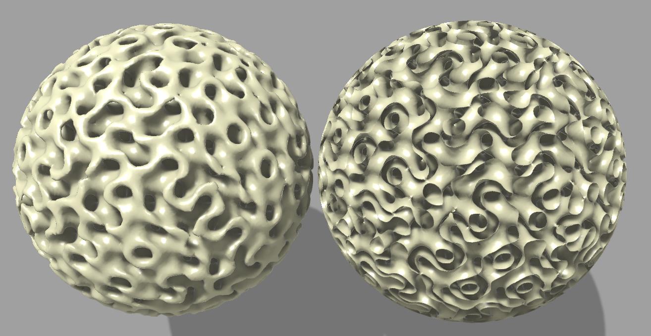
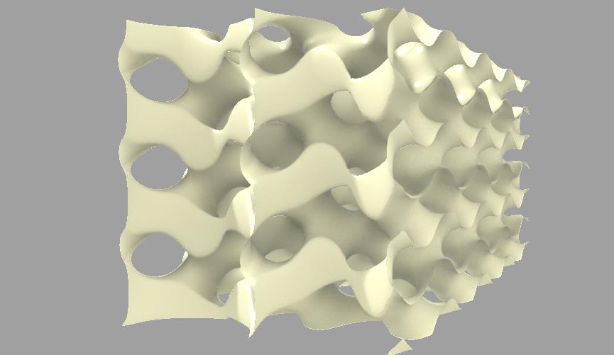
Isopod heat-exchanger and capped gyroids
Gyroid heat-exchanger seem to pop up more and more thanks to 3d printability. Isopod can be used to design one. The tricky bit is to keep the fluid-flows separate at the inlets and outlets.
Surfaces are defined by implicit functions as all points with a certain value (level), typically zero. TPMS (triply periodic minimal surfaces) produce values, which fluctuate between positive and negative (like a sine wave).
The custom TBO (Transition Boundary Object) component, takes a brep, an inner field (inside the brep) and and outer field as inputs, and generates a field as a combined output from these. If the inner field is a gyroid, and the outside field has a constant value everywhere, say “1.0” - then there are points with a zero value between the negative gyroid space inside the brep and the outside - this creates the capping surface. For positive gyroid spaces no such zero transition points exist - thus they are left open. The TBO takes an additional parameter to define the thickness of a transition zone to morph one field into the other more smoothly. The transition zone is inside the brep.
It is a good idea to normalize the TPMS functions, so that the the difference between the min and the max is 2 (typically this will result in a value domain of [-1, 1]). This makes the design process more predicable and easier to switch between different TPMS.
Here are examples for capping and a heat-exchanger. The domains for the different fluids in the heat-exchanger are separated by constant fields with value “1.0” for one fluid, and constant fields with value “-1.0” for the other fluid at the in- and outlets.
Capped TPMS.gh (33.7 KB)

HE TPMS 2.gh (74.6 KB)
3 Likes
How did you do the falloff on this one?
Can you please show how to do concentric ripples with Isopod?
I’d like to have ripples just within a sphere or other closed volume and control over the blend between the ripples and the rest of the object.


The overlay of the original mesh with the displaced mesh shows that there is a tiny bit of displacment also on the part of the mesh which is not inside the red sphere. Ho can this be avoided?
button_fade_ripple.gh (7.9 MB)
2 Likes
Hi Martin.
You created some custom c# scripts to handle the wave function.
Imo it would be simpler to directly write your whole function + fall-off in a single c# script, instead of relying in a sequence of fields “math” operations.
Your ^8 exponent lead to almost zero field strength, but “almost zero” is indeed not “zero”.
If you create a custom field that output a simple “1 or 0” output depending of the sign of a field, you can simply use that to multiply your field and avoid the appearing waves outside the sphere.
Thanks for the reply. The scripts are all from examples in this thread.
It is not clear to me how such a function would need to look like.
Hi Daniel, is there any progress with this topic? I would like to preserve the sharp edges of my input geometry, after creating a mesh from a field… what’s your current advice to do so?
I think you are looking for this.
You should be able to use the same script with the Implicit Displacement example, too.

4 Likes