Improvements for the MoveUVN dialog (Scale presets, Average + Colors)

The MoveUVN dialog is very useful, and more so if adding some small buttons for functionality that already exist in separate commands. Below the most frequent operations related to the use of this dialog.

SCALE PRESETS

In the MoveUVN dialog one can set the movement Scale by typing in a number.

Problem: Often one need to move spans of ControlPoints in UV direction, and then also making adjustments in the Normal direction. But UV movements are typically moved up to 10-100 times longer distances than the N movements, and so changing the Scale back and forth by editing the number field is both slow and error prone (plus it requires shift from mouse to keyboard and back again).

Solution: Add some basic presets under the number field. Perhaps also a slider. The following presets are useful and quick and easy to change by clicking the buttons:

AVERAGE POSITION

One typical adjustment of ControlPoints is to straighten out or flatten out the positions of the ControlPoints in a CP row. The dialog could have a cmd button for this, and so making it quick and simple to align all ControlPoints in a row to its average position for that direction with a One-Click button. Place such a button to the right of the each of the U, V and N sliders. See picture:

Usage: Often it’s good enough for a start to just quickly align all the CPs in a row to its average positions value (for a direction) instead of having to run SetPt and peek along the row to find a suitable point, and then pick that point as a reference point for alignment of the rest of the CPs on the row.

COLORED ISOCURVES

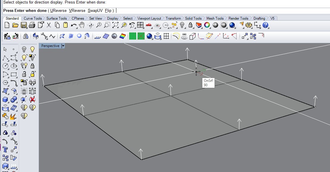
I also find it lacking that the UV directions are not visible (on surfaces) unless selecting a ControlPoint, or starting the Rebuild command (and then canceling, if only checking the UV directions). Tiresome.

When having complex surfaces one often have to make a “patchwork” in order to get good edge matching, but then it becomes time consuming to check the UV directions. And when finding out the directions, they are also difficult to remember.

For this reason I think it should be an option to display the Isocurves using the UV colors (different color for Isocurves in the different directions), and only add the direction arrows when activating a related command.

BUTTON COLOR

And while at it, please use UV-colors for the arrows on the U & V buttons as well. Seeing the color/directions on the surface should associate with the same color on the button, as to avoid logically processing a “translation” everytime focus is shifted from the surface to the dialog (tiring).

SMART-OPENING THE UVN DIALOG

ControlPoints On: At last, why not have the option (checkbox) to automagically activate ControlPoints when running/opening the MoveUVN dialog?

In general: All those separate (and in context, actually meaningless) extra commands and command sequences are time consuming and tiresome when having to repeat them over and over.:dizzy_face: Some commands are not used so frequently, at least not in the same work session, but commands and the dialog like MoveUVN can be in use for hours when working with complex shapes, and due to the lack of overview, mistakes are frequent.

COLORFUL

And please, use the direction colors all over the dialog, on text and symbols, like so:
[Edit: Added checkbox for UV colored Isocurves (and/or the lines between ControlPoints)]

:sunglasses:

// Rolf

5 Likes

Right on RIL- This is such a useful and much used tool- and could be so much more intuitive.

What would also simplify very much is if one could automatically select one or more rows of ControlPoints by clicking a button for desired UV direction.

It should work like this: Select one or more ControlPoints, and then click the button for the desired direction. Clicking the button should then auto-select all ControlPoints on any row that had any (one or more) ControlPoints selected. Like so:

Selection :


xx…
…x…

…x

Result from clicking Auto-select-V button =


xx…x…x
xx…x…x
xx…x…x
xx…x…x
xx…x…x
xx…x…x

Or, if clicking the Auto-select U button with the same selection:


xxxxxxxxxxxxxxxxxxxx

xxxxxxxxxxxxxxxxxxxx


The Auto-select UV buttons could be placed in the upper right corner of the dialog, looking something like this :

// Rolf

Hi Rolf - thanks, I’ll see if I can point out one or two things that might help in the meantime

  • you can make a display mode that has colored isocurves- I’ll attach mine.

UV Wires.ini (10.4 KB)

  • In V6, you can double-click on a control polygon segment to select a row of points. I find this does not mix all that well with the (default) ability to select objects that have points on, so I turned that off in Options > Mouse.

  • SelControlPointRegion lets you pick a UV rectangle og control points by setting the corners.

  • MoveUVN is modeless so it does not, in the current state of things, make sense to turn on control points when this dialog is up - it can be up all the time.

  • ‘Smoothing’ in MoveUVN may be at least partly what you are after in ‘Averaging’, for U and V anyhow.

  • Ultimately, I think where you are headed here is a control point editing mode , where you can get certain behaviors that are specific to this process. Generally Rhino is not ‘modey’ like this, but I can see the advantages in certain circumstances like point editing,

I’ll see what else I can come up with on reading your notes…

-Pascal

Hi @pascal,
Thank you for these tips, it seems helpful and I’ll try this asap.

One question: How do I make use of the ini-file? It should probably be placed in a certain folder, I guess? (I’m using R5)

// Rolf

Hi Rolf - open Options > View > DisplayModes and click on the Import button at the bottom - locate the ini file, import it and you should see a new display mode in your viewport title list when it’s all done.

2 Likes

Yes, I often have the dialog open (modeless) for a while, mostly for repairs (bulges) or Isocurve alignments (when “patching” more complex surfaces).

The dialog therefore would have to check the state of the ControlPoints when opening. If they already are turned on when opening the dialog, then disregard ControlPointsOn/Off altogether when closing the dialog.
But if not On when opening the dialog, or if the checkbox is modified while being open, then take appropriate action when closing the dialog.

Actually, no. When “patching” complex surfaces, then sometimes it’s not very easy to prepare the curves or the edges to get aligned isocurves.

When I have problems Matching surface edges, then often the underlaying problem is solved by aligning the Isocurves, and then it helps a lot to be able to :

A. pick a point which may serve a (better) reference position for the rest of the CP row, which may be in disorder (or sunken/hidden under the surface) along poorly Matched edges. Then you’re happy to have to pick only one CP and auto-select the rest (or averaging, without affecting any other rows).

B. quickly select an entire row (by picking only one CP and then auto-select the rest) as to align the isocurve(s) to the Isocurves of an adjacent surface.

B because aligned Isocurves seems to provide better start for successful MatchSrf results.

I think I use aligning Isocurves (B) most often, and it’s key to perfect surfaces, and it may sometimes (often?) be quicker to fix existing surfaces rather than very time consuming preparatory work which still would often result in non-aligned Isocurves.

And most important, with such more efficient Isocurve editing one may find it useful also to try fixing first attempt “trial” surfaces which ‘accidentally’ turns out to be close to a good match (requiring only minor adjustments).

// Rolf

RELATED STUFF TOGETHER

While at it, everyone who’s tried to adjust ControlPoints in , for example, Normal direction, especially if selection spans over adjacent surfaces, has experienced the surprise when one surface dives down and the other one rises… :slight_smile:

This happens to me kinda every time. Not to mention when something similar happens when adjusting U and V direction, if not CPs from two surfaces in the same selection, but when switching from adjusting one surface to adjusting an adjacent surface, which due to murphy’s law, of course has the directions “the other way”.

So it follows that the Dir command (or, “Show Direction”) and checkboxes for Flip Directions should be in the same dialog, like so:

Edit: Labels “Avr” and “Sel” added for clarity.

In the best of worlds the FlipDir Checkboxes be grayed out when no one or when multiple surfaces are selected (avoiding mistakes).

And, modalless is what makes such a dialog so much more powerful, since all these related commands stay directly available, when needed the most. Which is the overall main point in this entire thread, I guess


Edit: I just realized that the Dir command allows for, not only Flipping directions, but also Swapping directions, so, another set of (“SwapDir”) CheckBoxes should be added to the right of those pictured above

Fotnote: For some reason the UV arrows don’t show up when selecting one (1) surface only with the Dir command, resulting in that you don’t actually know what you’re doing if Flipping (UReverse or VReverse) or Swapping the UV directions (since arrows are shown only for Normal direction). Bug?

// Rolf

2 Likes

This is nerdy as shit, and since UVN is also nerdy as shit I absolutely love it. Great thinking RIL!

I’d add a couple of wishes here:

  • Straighten between first-last U or V selected (like if you drew a straight line between the first and last of the points selected and then you snap the middle points to that line to nearest point.

  • Soft move selected points.

3 Likes

I like your color idea—Mark

1 Like

we are also assuming that the colors will be visible in the points/hulls when UVN window is open? Can we toggle the display mode from the UVN window? :slight_smile:

2 Likes

Hi Rolf - I do not see this here, I get a white ‘normal’ arrow and red/green U/V arrows - now, they may be coincident with isocurves or edges, which admittedly makes them hard to see sometimes, but here at least, they do display…

You don’t get anything like that? Note they will not show for a polysurface except on the cursor as you move it over the different faces.

-Pascal

Hi Rolf -

Can you make a simple example, please, to help my simple brain with this one?

If the surfaces have the same structure, MatchSrf should align the isos if ‘Match by closest points’ is not set. Does that do anything you like?

thanks,
-Pascal

@pascal, Using Rhino5, SR13, and std Viewport settings, in the screenshot below I used Ghosted, I see no such arrows for a single surface, arrows displayed only for the haircross.

I tried all Viewport modes. See picture :

// Rolf

OK, that is correct for V5, yes.

-Pascal

Yup. A made up an example where the CPs are in “disarray” and at least two of them are “under the surface.” In this case, the selected CP would be a perfect "reference CP for the rest of the CPs in the (edge) row, if the all the other CPs could be aligned to this one in one shot.

Noteworthy is that ending up with a situation like this isn’t very unusual when messing up and trying to correct surfaces with very complex curvatures.

Hm, interesting. I thought I had tried all those combinations, but I’ll try again asap.

// Rolf

Hi Rolf - what would the alignment be though? A point is too loose a constraint, it seems to me, by itself - can you show me the end result of the operation?

thanks,

-Pascal

OK, it may not be obvious what the command would do.

The context though was having “Average” buttons for each UVN direction, and in this case assuming that the Y-axis = V, then, when pressing “Average” for V direction, the CPs would be aligned along the (V) axis, that is, both U and N directions would adjust along a straight line. Like so:

But I suspect that you want even more functionality than that ( :slight_smile: ), so you may well be able to talk me into having both Single direction buttons and Combination direction buttons, like AverageV(UN) and AverageU(VN) as well as single directions AverageU (only), AverageV (only) and AverageN (only) buttons separately. :slight_smile:

Edit: But, the combinations could be achieved by two clicks as well, for AverageV(UN) you’d click AverageV(U) and then AverageV(N). The initial V meaning “along V” direction, adjusting the CPs in (U) and (N) direction respectively.
// Rolf

OK, so the result is the points fall on a best-fit line between the first and last points in the row, correct? Are the points also averaged along this line - evenly spaced, or are they simply pulled to the line by closest points? We may get partway there, as far as the functionality goes, with this script - give it a try and see if the result is what you like - I understand the UI is not integrated with anything…

AlignGrips.zip (1.7 KB)

Save the rvb file out of the zip archive, then drag and drop it onto Rhino - this will add an alias for

AlignGrips

See if that does anything good for the moment. Probably not hard to add a best fit line as a target as well.

-Pascal

Yes. “Average” would of course need the surface as a reference as well (the direction of the to-be-edge, since the direction of the edge may not be orthogonal).

Hm, that would be adjusting in 3 directions at once. I would hesitate doing so. Doing “too much” in one shot/command would probably make it difficult even to name the command, unless you write a whole poem describing what happens if you press that button. :slight_smile:

It’d be more “secure” to work only in one “plane” at the time. Also, the more “granulated” functionality, the more useful the individual commands can be in other contexts as well.

I’ll try it out asap.

Edit: Well, a name for a command that could also even out the spacing could have the name AlignGrips3D, but as said, I would probably feel more safe doing the spacing separately.

// Rolf