I am manufacturing the sides for a bumper that will be laser cut and then folded in several steps.
but I am having a series of problems.
I can create the ruled surface using the DevLoft command
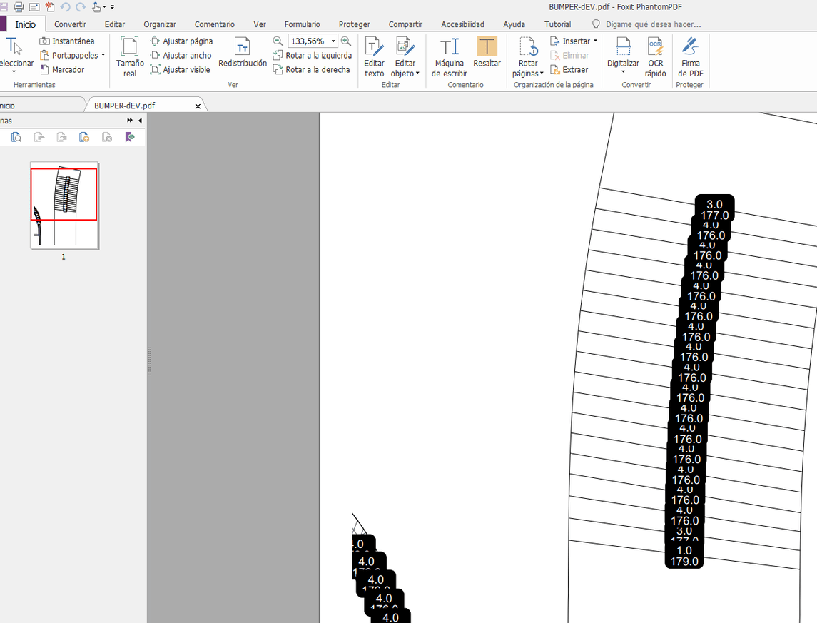
But this generates two problems. One of them is that it creates too many isocurves and they don’t help me to use them as folding guide lines. I also need to unroll the surface and this generates two more problems: (A) the original isocurves of the piece change; which is very difficult to know where to mark the folding lines to create the piece thought and (B) it is difficult to identify how the piece goes once deployed, for this I must make a cut on one side to identify the correct orientation.
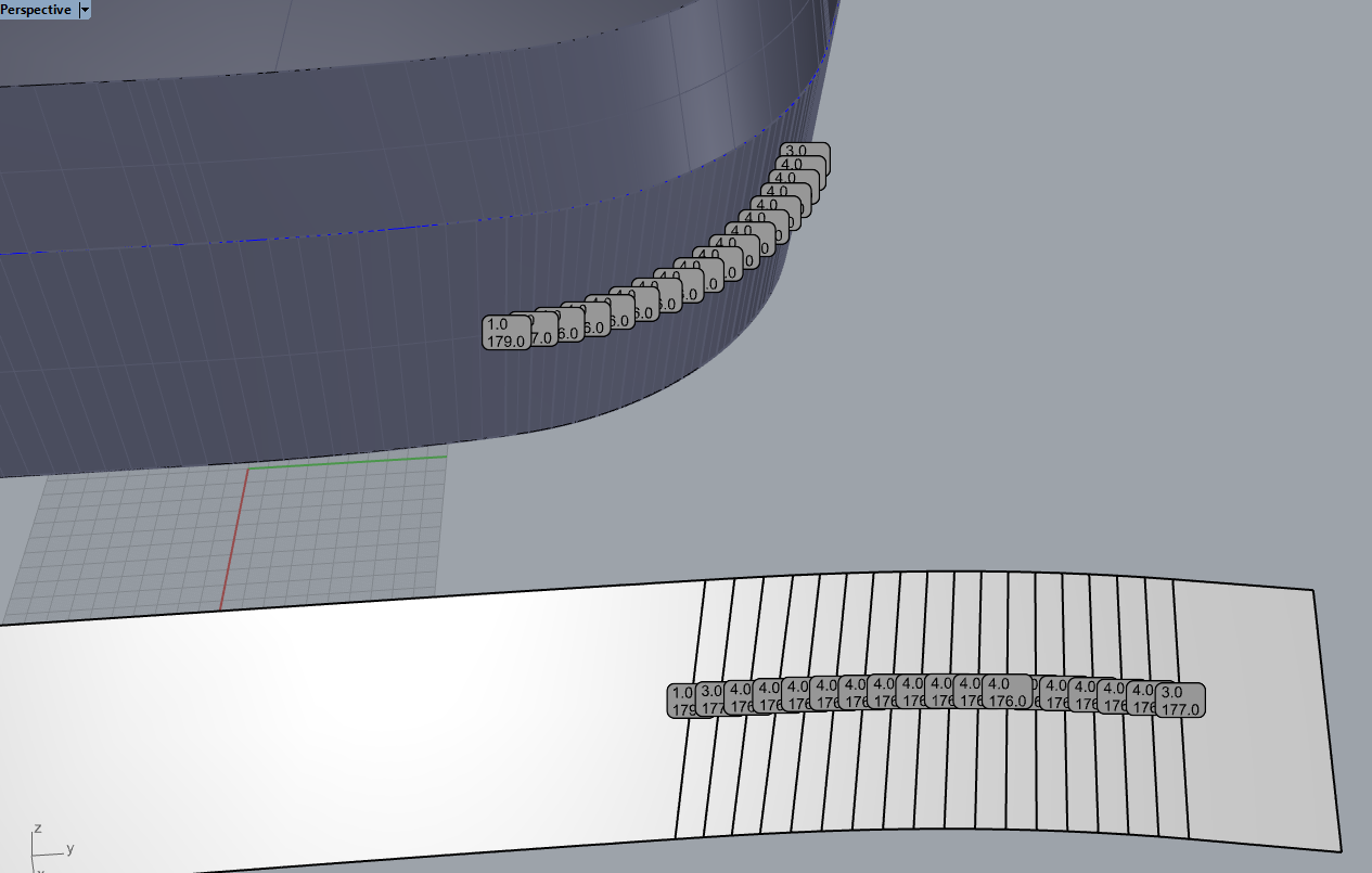
Once I have this, I must generate a ruled polysurface to create flat faces and then I must find every angle between those surfaces to know how much to fold the piece. I achieve this using the Rebuild commands in “grade 1” and DivideAlongCreases.
The idea of all this would be a tool that unroll a polysurface with flat faces with their respective angles between them, and highlight the edges by colors; It would help me a lot.
Hello - you can add curves to the selection to unroll, that should, I think get you the information you need on the unrolled part…? BUMPER-dEV_Maybe.3dm (267.6 KB)
@vikthor - here is a script that will add a dot with the angle information to selected edges - these can be unrolled with the faceted objects.