Hi Pascal,
I’m not quite sure I understand… Do you have a file or maybe an image?
Hi Pascal,
I’m not quite sure I understand… Do you have a file or maybe an image?
Hi Lagom -
l
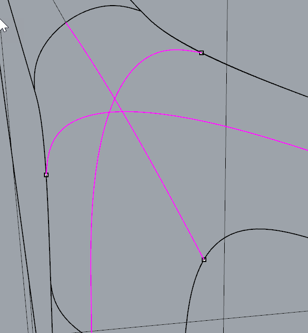
Here the box is randomly deformed to the corner is at an 'odd angle, and the 'fillet’s have different radii -
I can guess about where that convergence point ought to fall but it is a guess from say, averaging the curves closest points to one another:

I can then work backwards from that point to get the converging edge curves but there is probably a better way… Finding that point is always the hardest part to get right, in my experience.
-Pascal
Those isocurves are very similar to t-spline T joint iso. Great inspiration, thanks Lagom!
Hi @Lagom,
I guess I have the same problem with @pascal
Cause the arc corners have the same radius, but conic corners don’t.
I did G2 for the curves where the highlighted points are located on and the points are the midpoints of these curves.
It seems that the mid curves of these three blue surfaces are not “straight” as one of the iso curves; instead, they are “curved”…
Anyways, I also struggle to find the convergence point as Pascal explained.
Yanchen
Hi Zhao,
so, in other words, the blue surfaces running up to that corner have different curvature (start and end section are identical, but the lengths of all three are different), so that when you blend a curve like in that example I did, the blend curves do not intersect, as they inherit a different curvature (mine were all equal, which means they are self-symmetric and intersect).
Phew… I’d use SolidWorks ; )
No, I actually think there was a typical solution for this one in NURBS. I need to think a bit about how that was. The Canon PIXMA ip4000 printers from like 10 years ago had that sort of design language, the on/off button sat in one of the corners…
Hi Pascal,
thanks, I see what you mean. Off the cuff, I would think it’s a bit like handling a Y-branch
with the difference that one does not draw a straight line to the centre, but a blend curve from the peak of the blue surface to the yellow surface, and then uses the same patching method. But I have not dealt with a “quirky” branch like the one you’re showing yet : (

Oh my…that guy is beautiful!
Yea, I feel like sometimes, a similar function in SolidWorks can create smoother surfaces…not sure if that’s an illusion.
Hi lagdom - yes, I see the structure is the same, but on a level Y branch it is not hard to find this point:

If the three branches are not level - at odd angles - that replicates the condition on a non-square corner, or if the branches are not straight, it gets trickier i.e I think this is difficult to solve in the more general case even if in theory there is a magic convergence point. I thought maybe you had a trick =).
-Pascal
Hi Yanchen,
I remembered a typical solution for this form language. It originated from the patch principle for making G2 “ball corners” (which then of course aren’t ball corners any longer) and similar bits.
(oops, should say magenta surface, that’s just a single one - too late in the day…)
Hi Pascal,
if you have a raw file, I may have a trick ; )
Hi Lagom - your example above is probably as good as any - but here’s a file with odd angles and non-matching blends - in your examples it looks like you have an excellent way to nail down that elusive point, but I’m too dense to see how you’re getting it. I go after this with a slightly different layout - but it should amount to the same thing, I think - that is, I usually use six surfaces that converge at the point but are only half the width of the existing fillets, not the three full width surfaces plus three squares layout you show - I don’t know if one is better, but yours do look clean.
SetbackSetup.3dm (94.4 KB)
-Pascal
Hi Lagom,
Your example looks fantastic, thank you so much for the demo!
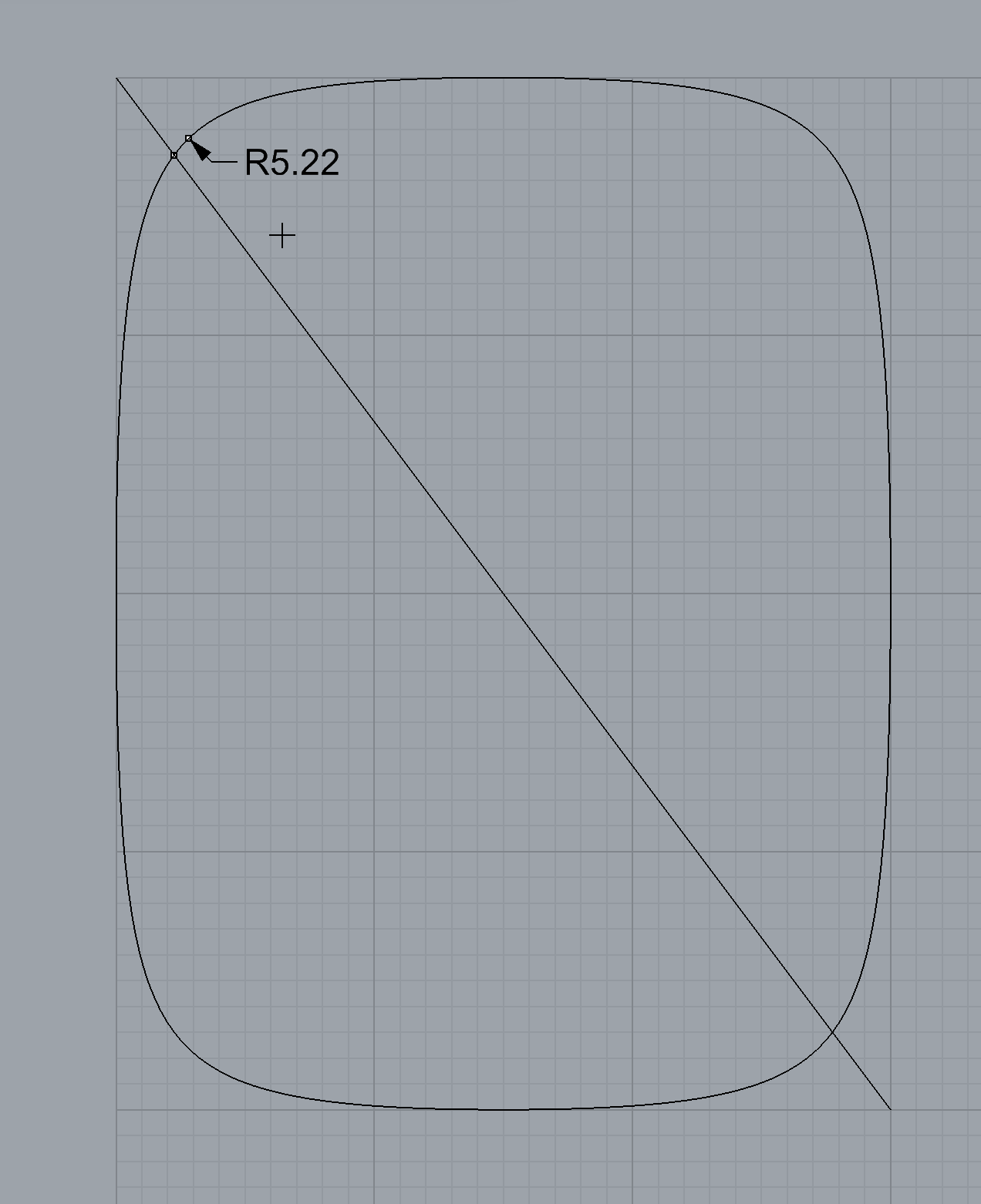
I have no idea any of these principles behind each of the function. The pic below shows the point I used earlier and the min radius point you stressed. How do you find the min radius? I just used measure radius and of course not precise. I guess the min radius point should be the intersection of the conic and the line that connect the conic vertex and focus, but how to find it?
Also when massaging the control points, is it judged by the raw eye? And massage the control points to achieve…what?
Much thanks!
Yanchen
Hi @pascal,
i use a very uncommon method to find that point in the middle…and to fill such holes 
Your case: SetbackSetup.3dm (413.0 KB)
Case from first post: Loft.3dm (391.0 KB)
Does it blend ?
c.
Hi Clement - I like your point! Using that I can make a very decent - more traditional than yours, I would say(!) - six surface layout

But still, how do you arrive at 2 units for the normals? Is there some trial and error?
thanks,
-Pascal
@pascal, i guess it can be any length in the beginning. The trick is to define 2 triangles, i did one from the normal end points and one from the normal start points. Then got the centers of these triangles to build a line. The point in question could be in multiple positions on that line. I think the height of the multiblend could be adjusted along and around that line when i had VSR Demo installed.
Getting a good height can also be done by making an initial patch fill and intersecting the line made from the triangle centers with it. To create the 3 initial blend curves, i just worked like in your picture but created the blend curves from the 3 fillets middle isopharms to the opposite edge midpoints. I have a script to blend perpendicular from an edge, through a point and to another curve end (the middle isopharm of the blend surfaces used as edges). I guess this also can be done using _InterpCrv and _StartTangent, then pick on the point, then _EndTangent. This way all 3 blend curves are intersecting at the height point.
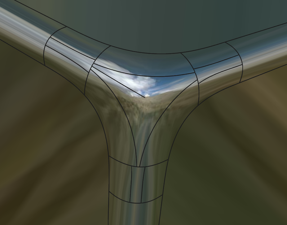
The fun part about my method using a circular _Loft to create the actual corner center is that you do not have to mess with tangency between the 6 faces in your picture. Just split the 3 blend curves at the point and loft. If the height of the point is at a good position, the loft needs no fixing at the pole. But this can be done quickly by projecting the controlpoints (center and first row) into a plane perpendicular to the height line. The rest can be filled out using just blends. Below is another example:
btw. can Rhino 6 get some kind of Multiblend LabsTool ? …or the _MatchSrf command can be further improved to support _MultipleMatches with 4 Edges using higher continuity ?
c.
Thanks Clement - I used a script to average the three normals to get that diagonal line - same idea… so I know the point goes on that line… but where? - you just nailed a good elevation for it. Should be easier…
I like the loft-n-blend technique!
@clement - V6 will not have a multiblend… MatchSrf is essentially the same but with History enabled (which brings its own set of problems but it is very useful none-the-less) and allows matching without an edge as the target - between the two of those tweaks it is actually quite a useful tool now.
-Pascal
Hi Pascal,
thanks for the file, I look at it as soon as there is time.
The elusive point finds itself; the corner cases I showed were symmetrical as is the Y-branch. Even Yanchen’s setback issue is trivial, if one uses the “setbacks must end on smallest radius point, then flattest of the three corners to be patched” principle. I’m designing rather boring products with a lot of symmetries, so I think your example warrants a “sculpting approach”, where in each new case it will be different. It’s challenging and interesting!
Hi Yanchen,
you can have software like Matlab calculate where the smallest radius point is (arc length calculation), or use a visual indication like what you show to then eyeball it, which in my view works rather well if you zoom in sufficiently. The thing with setbacks like yours is that you want to get the best surface flow and as few isocurves as possible by minimising the corner area to be filled. Massaging control points is necessary to achieve G2 surface continuity (according to the tolerances you’re working towards, meaning what angle is acceptable depending on product, manufacturing method and of course size - you probably won’t bother with G2 if the setback corner is tiny in reality or if the material hides minimal discontinuities).
Creo or SolidWorks have a tool that patches these regions, like Rhino and Alias have, but when you analyse the former two’s results, they also often enjoy surface perturbations. This is where massaging control points can achieve what software still can’t always achieve, in my view. Ask technical surfacers working on class-A surfaces for aircraft or cars ; )
Will it blend? Luckily, it does https://www.youtube.com/watch?v=BPytl4pwjjo ; )