I need the geodesic curves along some arbitrary surface, e.g. cylindrical or conical, but I don´t want the “shortest path” geodesics like those implemented in Geodesic component. Such component always returns the “global” shortest path curve between two points in the surface. What I need is the paths between the two yellow points illustrated in the image as red or blue lines (taken from this old GH forum thread):
The reply by paco g on October 19, 2011 at 8:14am contains an explanatory GH file that I´ve modified and attached here: ConeGeodesics.gh (20.4 KB). You can play with the bi-dimensional sliders to see that the “globally” shortest path is always generated instead of the more “local” one.
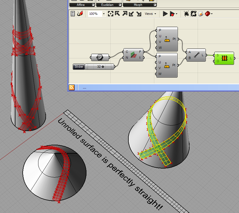
In an older thread, javier zaratiegui shared a Rhino plugin toycar.rhp (16.5 KB) to draw the “local” geodesics that I´m looking for… but I can´t figure it out how he could access the Rhino plugin from GH… or perhaps he didn´t. From the snapshot he showed (see below), it seems that the geodesic lines were drawn first in Rhino and then used from GH, am I right? If not, would you tell me how I can draw such lines from GH? Thanks!
For the general case … well … you need the ShortPath Method. That said you can extend the ShortPath curve and get the “equivalent” 4 Curves as done in the demo above.
The extend is maybe handy in caces with Surfaces closed in U or V or both … where the ShortPath may not be the desired result.
But … this is a bit more fuzzy: what happens if the extend yields points on the same IsoCurve? (i.e. points that either their u or v are the same). Meaning that the 4 Curves as above are not a given in any situation.
Hi Pfotiad0, thanks for your comments and kind script .
I´m trying to create a parametric model of some grid structure like this one but without the gap between top and bottom cones. In such structure, the helical beams would turn several times around the conical surface before reaching the top. Thus, shortest path solutions will not work.
Ideally, I need a solution that yields the full path directly. For example, the ToyCarPath tool that I found before (it can be easily installed by drag & dropping it into Rhino). To better illustrate this, I´ve baked the cylindrical surface and ran the ToyCarPath command on it using your script (black path):
Unfortunately, I don´t know how to access ToyCar from GH. Do you know how? Or perhaps, you know a better design approach to model the conical grid structure above.
Well … to be honest I never work with add-ons (if the Toy whatever thingy is an add-on). Plus I don’t work with R6 (in case that the Toy is a GH/R6 component).
Other than that I work solely via code (C#). If you want a code based solution on “similar” grids (so to speak) notify.
Based on your posted image … In fact doing anything (general case: working in BrepFaces) similar is rather easy: You divide the underlying Surface (or the Surface) into a Tree of points (say branches “in u”, items “in v”) and then you combine them according some logic. Forget the target … just draw in a piece of parer a rectangular grid (of dots), imagine some sort of pattern, do the pattern according possibly some special restrictions (like your void zone shown), take into account the potential closure in u/v … and then get the desired result (pieces, trusses, meshes or some other).
Hi Peter, thanks for your help and willingness to share some C# code solution. I´ll let you know if necessary
Ideally, the solution should work for any revolution surface. If it is not possible, conical shapes would be enough at this early stage of the project.
I thought about a solution based on geodesic lines because the angle between the helical beams and the cone axis remains constant. This way all beams will withstand the same loads if self-weight is neglected and the structure is axially loaded at top.
I´m working in an iterative solution that always keeps the same angle with the revolution axis. Briefly, it obtains the next level points of the grid from the intersection between two cones (with vertices at adjacent points in current level) and the surface of revolution. It is hard to explain by writing and it is work in progress yet. However, loops in GH are a bit painful (I´m using Anemone).
Do you know a simpler way (loop-less) to maintain the same arbitrary angle with the revolution axis? Thanks a lot!
Well … see that thing over there? Is The Fence. Depending on which side you are things are very easy (via code) or maybe not so easy. For instance dealing with any loop(s) is just a matter of adding some lines more (that’s especially true when recursive solutions are on demand). On the other hand for complex and CPU intensive things … code is the only way to hapiness. On the other hand things are done by teams these days … meaning the obvious.
As an AEC pro I advice to liberate yourself from similar (í.e. “equal loads”) constrains … and do your point grid the trad way: divide a BrepFace, that is (this yields points or null if the BrepFace doesn’t contain the point in question). On the other hand … these days any rational thinking is a big anathema … meaning that clients demand more and more topologies that very rarely can yield any “optimum load” policy. On the other hand … in most of (non blob) cases a tensile membrane is the way to go.
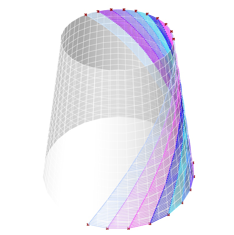
So (a) fully get the gist of what a DataTree is and (b) get a piece of paper and design any pattern you want (plus take into account the closure in U/V : see the blue/cyan pieces that require a bit more attention):
Plus: if the “envelope” is irregular (the norm these days) and the LBS has a thickness (kinda like a W truss etc etc) … then clash issues are 10000 times more important to deal with than any "“ideal” strut arrangement in space.
And a true story (having the “optimum” chimera in mind): A client asked me to evaluate a concept of a big tensegrity truss proposed (years ago) by someone else … er … with EFTE on top (I hate that thing). I.e. he was evaluating the possibility to resurrect the dead meat. Client has many “advisors”: all of them very positive for such a solution. My report was very short and gratis: don’t do it at any cost. Client asked in depth explanations. I said: a concept without all the nuts and all the bolts is a Ferrari without an engine: you are fooled - on purpose - to believe that lightness is “reasonably” affortable (kinda buying a F1 car for the street). The solution in question appears on first sight rational but the special parts - not shown in the concept - required (multi variable tube-cable connections etc etc) raise the cost almost 3 times VS a MERO KK solution: so is more than obvious why you are advised to do it.
Hi Peter, thanks for your contributions and experiences shared.
Sorry, but my project is research related, fortunately I have no clients nor advisors telling me what are they going to pay for and what they aren’t
I just want to compare several tower-like alternatives for some research project. In tall buildings and tall towers (e.g. for wind power generation) weight efficiency is an issue. This is the reason of my obsesion for equal angles and geodesic stuff.
I already have some UV meshing based designs, but now only the “equal angles” design is left. I’m having some success in the iterative approach (based on Anemone), but I’m having some problems by nesting two “for” loops. If I don’t succeed today I would open a new thread about it. I hope not need to bother you with this looping issue
Hmm … see the sketch above and imagine doing the dots with index 1 for even branches and 0 for odd. Kind of zig-zag “near” the IsoCurve that suits you best. Then you combine each dot with the previous and the next and you get the 2 related short paths (per, say, even branches). Then you extend them and you get your geo chaos. Then is a classic Curve/Curve ccx task.
Hi Peter, your script and C# code look very nice and it is very fast too! Thank you very much, I will try what you say with the extend option once I debug my buggy-looping approach. I think I will start a new thread soon before turning crazy , stay tuned…
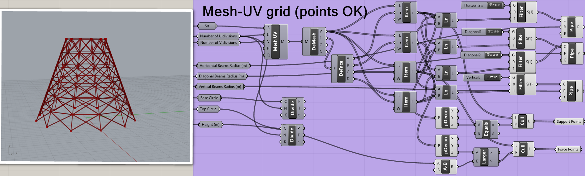
By the way, this is one of the non-loop design options I´ve found so far (Mesh-UV based). As you can see angles at top are very different from the ones at the base.
Hi and thanks again, I think I can´t do what I want using your script and the “shortpath and extend approach”. When I try to extend from uv point 1 (0,0) to some other uv point 2 the curve usually bounces back instead of keep going up until it reaches the cylinder top. Check this example:
… and indeed the ExtendOnSurface Method yields this bounce back result: one should expect the opposite mind … meaning that this idea is just another stupid thingy.
BTW: I fully understand your quest for non truss based LBS solutions … but nothing beats a good old W truss (most notably these days where carbon fibre is available to the masses meaning ultra light CF tubes etc etc ). The old thing again: the more things change the more stay the same.
On the other hand … since you can have a ShortPath on a cone/tube (“top to bottom”) … is your issue just about how to have a “grid” of these (i.e. what u1/v1 - u2/v2 values to use) ? If so time for V1B
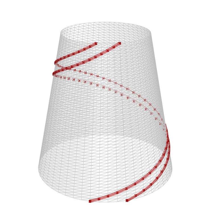
Added just 6 lines of code: a list of v1 values are made (step = 1/(double) div) and a clone list v2 just shifted in a classic circular loop. Result (I’ll add the “symmetric” short paths in the V1B).
Not sure if this is relevant, but I played around a bit with a Kangaroo method that might be of use.
I haven’t tested whether the strips here are of a constant width, but their edge curves should be geodesic to the cone?
I´m sorry, but my issue requires that the helical (or diagonal) beams be able to turn around the conical structure (even several times). It seems that your “top to bottom” approach uses the geodesic (shortest) path, and so, it cannot turn many times.
I´m close to finish my loop-based solution. It iteratively computes first the intersection curve between two cones and then the intersection of the later with the surface to determine the next level points. As you can see, it is able to turn whatever the required times around the cone and, at the same time, maintain a constant angle of the helical beams with the vertical axis. Here is my first animation in GH, sorry for the bad quality!
Hi Nick, thanks for your kind contribution! It looks very interesting. I´ve tried to take a quick look, but I have a couple of plugins missing. I will look for and install them later, and will let you know if it works. Thanks again!
Apologies. Here is a quick edit that wraps a single strip but only uses native GH/R6 components. I can help update it for multiple strips a bit later, but this will at least introduce the idea to see if it’s of use to you.
Hi Nick, I installed MeshEdit2000, and played a bit with your solution. Unfortunately, I was not able to obtain geodesics that turn around the cone more than 180 degrees, i.e. like the thin black lines in the cylinder from post number 3. Is this possible with your solution? Thanks!!
If you are solely after cones … this is solvable in real-time (say 5 milliseconds for 1+K points) via classic trigonometry and some recursion. Notify if you want a C# that cuts the mustard on that matter. But the gains in dollars for such a LBS would be rather academic. Would be faaaaaaaaaaar more challenging and meaningful to design (not with Rhino) a proper “modular” node for your HPE/HEB/HEA/IPN/etc members.
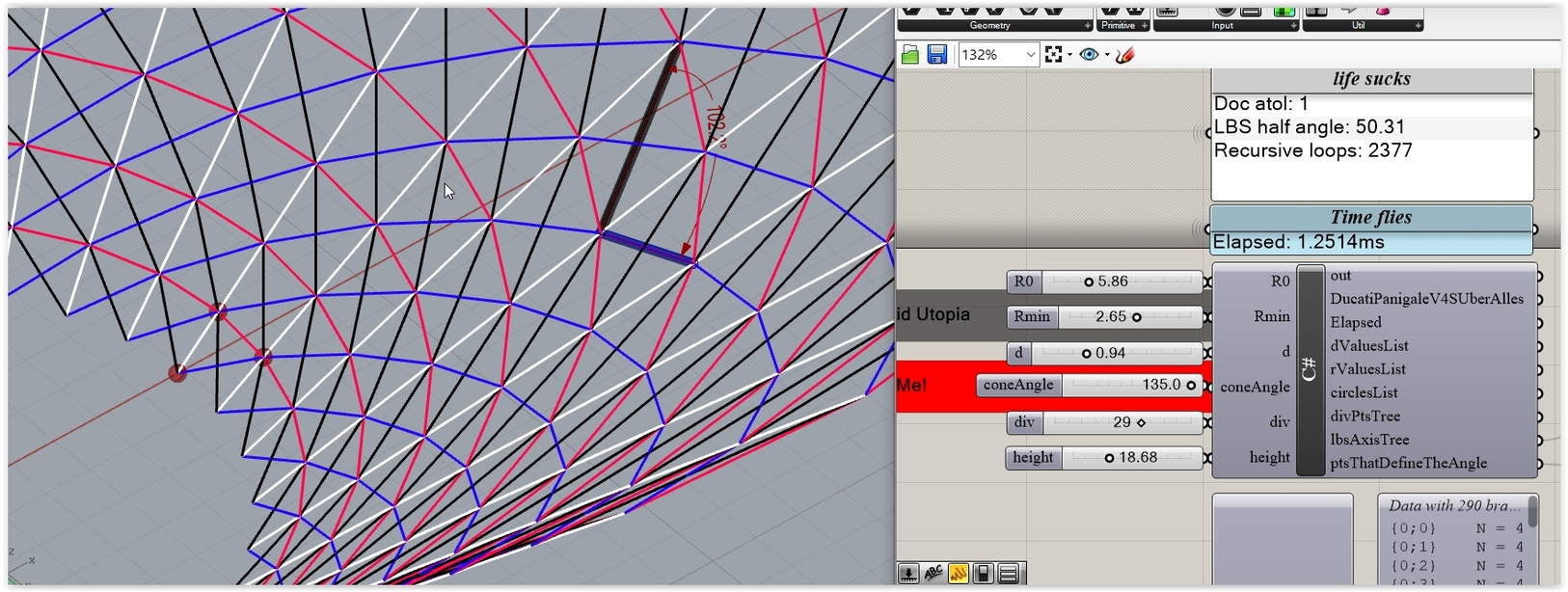
Other than that here’s what are you after:
Starting from R0 and given a step d and pts according some division value … you can get easily R1 and the bottom most white and red pair. So … you are after X that yields the upper (i.e. next) white/red pair where their angle is the same with the bottom pair. And so on … until you reach some max H (that is the sum of all solved d’s). You can solve this via trigo or classic Plane/Plane ccx stuff.
@PeterFotiadis - Learning a bunch from your posts, and don’t intend to undermine them!
But just to follow up on the previous question, if tracing the actual mesh edges is desired, a mesh walking algorithm may be sufficient? Here’s a sample:
It’s a balance: how fast you want to get results VS the complexity of the whole approach. For instance the (WIP) thingy that I proposed above is very simple: a few lines of code in fact …
… and is rather the fastest way to deal with a similar issue. Truth is that nobody would be after a zillion nodes for some sort of AEC tower… but if this is only the prelude (towards a real-life LBS system that includes FEA and many other things) … well … every millisecond counts.
On the other hand: assume that the one way of the other we get a LBS with “steady” angles (within a given atol obviously: atol = RhinoDoc.ActiveDoc.ModelAngleToleranceRadians) and then we proceed further on. But wait … what means in real life such an angle? Is it some abstract value that if achieved everything is OK? Far from that: you should outline/design a realistic node as well (in most of cases with big members involved). So … the smaller the angle the more arbitary checks are required. Count the fireproofing layer as well that in several real-life cases is “bigger” than the protected member. Etc etc.
More soon;
Update:
The WIP thing goes well (1K nodes solved - on average - in 1-2 milliseconds). LBS angle reported is the half angle (I like confusion).
Must cut that time by a factor of 5 (case: tower with 5667777766789999 nodes). Must control the angle accuracy with some better way (for those working at NASA, that is). See the 68.7 angle that has …er … a big difference VS the 68.8 angle (this may result a million dollars gain or even a billion or a zillion (LOL)).
Question is: what kind of modes (i.e lbs axis member combos) are required? Like the one shown? Maybe some other(s)? What other(s)? (sketch required).
Good point, and I should be more clear for the sake of the thread.
By “sufficient” I meant whether @Vigardo needs to be able to set a variety of initial wrap angles, or just use the angle set by the diagonal of the mesh faces. In the latter, they are limited to a solution space that is much less nuanced and depends on the mesh subdivision, but I suppose if the structure is set, this may be simple enough. Not at all implying your solution was overly complicated. Looking forward to tinkering with your work above - super nice!

 .
.