Hello,
I am trying to connect multiple Ellipsoids with a circle in such a way that I can create an intake manifold. The purpose of this is to collect a liquid and distribute it to the elliptic pipes.
I tryed using the loft tool and the network surface tool, but i coudlnt get it to work.
I just started to learn Rhino/Grasshopper so im still figuring out how basic things work.
Any help is highly appreciated.
Flachrohrgeometrie.gh (14.6 KB)
Can you sketch your design intent for the transition?
Have you considered learning how to create the geometry in Rhino directly before trying to do it in Grasshopper.
I don’t think lofting between the array of ellipses and the circle will work out well. It would look something like this, which is absurdly complex to make.

Solid Union (in cyan group below) fails to join these 28 lofts. By the way, I found and removed these bits that were splitting the ellipses into three segments for no apparent reason?

More practical, I think, is something like this? Simple. Perhaps rounded corners on the rectangle?
Flachrohrgeometrie_2019Nov28a.gh (22.5 KB)

Thank you for your answer!
I intend to connect the surfaces so a fluid can be equally distributed into small channels. After i have the surface iplaned to offset it and construct some kind of lattice structure into the space between the oval tubes.
I havent tryed to create it in Rhino, because i need to be able to vary the tube geometry as well as the distances between them
Thank you a lot Joseph!
I guess youre right, the design will be too comlicated, especially because I plan to print it with an powder bed fusion system.
I split the ellipses into segments with the background of beeing able to select parts of the surface for the construction of a lattice structure (the lattice is there to ensure mechanical stability and to enhance heat transfer).
Your solution is indeed an option, the only problem is that the fluid will probably not be distributet equally, but maybe i can introduce some additional geometry to handle the problem.
I appreceate your incredible fast answer.
actually i could take your shape and simply increase the distance of the circle so the angle will decrease.
This one creates a “collar” (orange group) by lofting the circle with a square of the same area. The yellow group sorts the ellipses by row (branches), since they are not sequential in the X direction. The white group divides the square with rectangles, organized in rows and columns to match the ellipses. There is a slider to adjust the seam of the ellipses to smooth the lofting with the rectangles (actually Ruled Surface, not Loft) in the purple group. Finally, the “collar” is joined to all the “lofted” ellipses to create a “Open Brep”.
There is no effort made here toward a solid “Closed Brep”, needed for 3D printing.
Flachrohrgeometrie_2019Nov28b.gh (30.7 KB)
Hi!
Your input was really helpful, thank you Joseph.
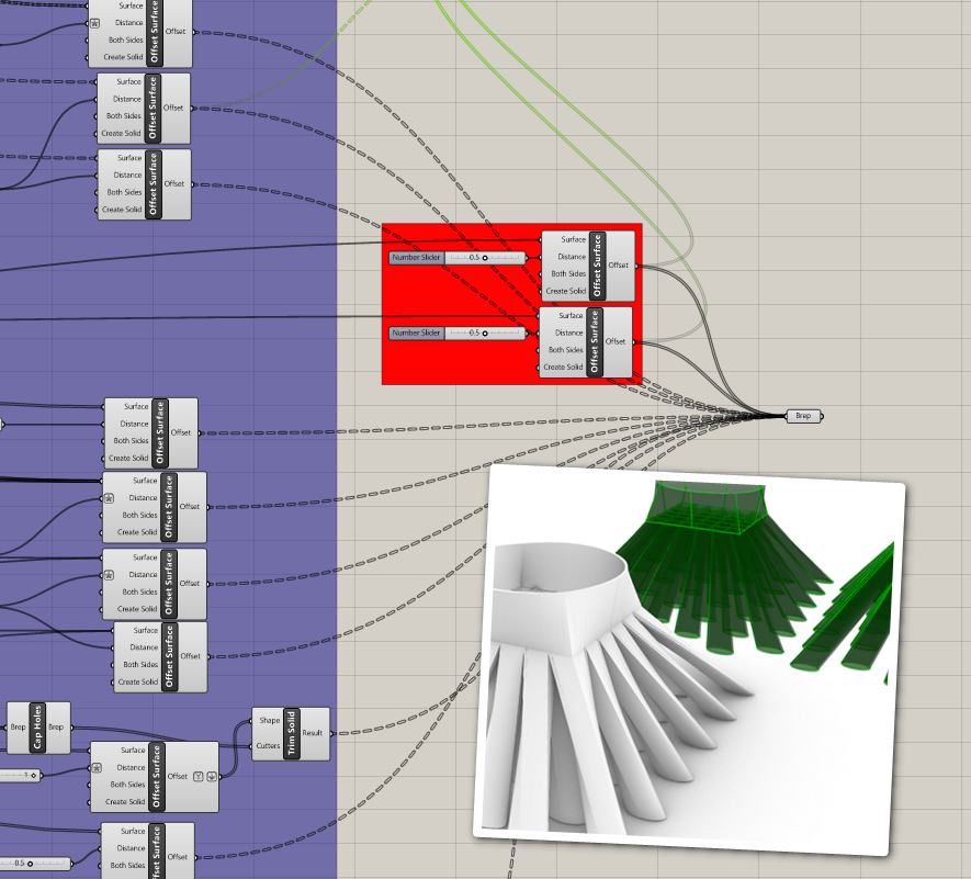
I now have constructed the heat exchanger core and tryed to offset all the surfaces in order to get a printable part.
But i didnt manage to get a manifold/watertight body for the fluid collector. I tryed using the offset surface tool, which worked ok for the other surfaces, but not for the loft between the rectangles and the ellipsoids.
Can someone help me with this problem?
Best regards
Benjamin
Flachrohrgeometrie_QuaderAnschluss.gh (90.3 KB)