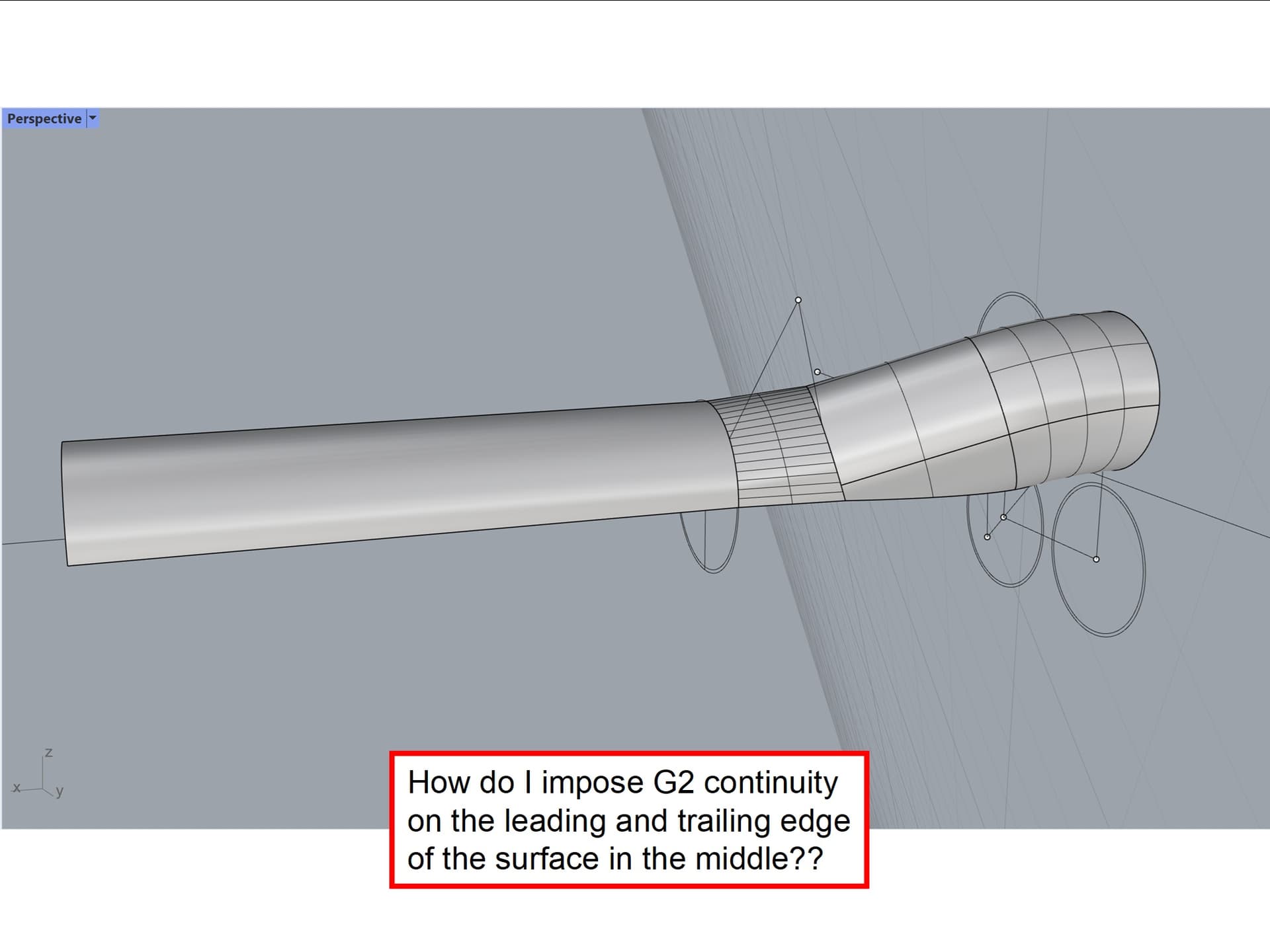
how do I impose G2 continuity on the fore and aft edges of the surface shown in the image
below??
Art
how do I impose G2 continuity on the fore and aft edges of the surface shown in the image
below??
Art
Use MatchSrf with the MultipleMatches option.
You can also apply MatchSrf twice, once at each end. Use the “Curvature” option in “Preserve other end”. MatchSrf will automatically increase the degree and number of control points if needed.
Thanks guys for the quick responses!! David, your “highlighting” went a long way to keeping this wayward student headed in generally the right direction.
using MatchSrf proved a challenge; see attached collage!! concerned about potentially over constraining the basic geometry I extended both tubes, intersected & trimmed both, and concluded there should be enough space for G2 edge conditions. to confirm my conclusion, the two surfaces were filleted with a 1.375" radius with no problem. that being the case, clearly a case of operator error. what are the most frequent causes of the software getting confused? the original connecting surface was created with two arcs and a straight line using the two rail sweep command; is there a better approach or one that leaves fewer artifacts?
Art
The twisted surface in MatchSrf is the result of picking the surfaces on opposite sides.
You can also use BlendSrf to create the blending surface. Here is the result of BlendSrf for similar geometry:
David-
thanks for your note! given the known limitations of MatchSrf, I gave up on it and moved on to the "variable
radius fillet surface". your tip on BlendSrf is greatly appreciated; the more tools in the toolbox the better!!
MatchSrf is the most reliable when the surfaces are nearly matched already and require only a small amount of movement to get an accurate match.
The twisted surface in MatchSrf is the result of picking the surfaces on opposite sides. “picking the surfaces on opposite sides”? with two surfaces to match, how do I avoid picking two surfaces on either side of the interface??
be well
Art