Help with visualizing mesh geometries

Hi,

I have to display tape geometries(mesh) that lie on any sort of 3d shapes (molds). There could be multiple layers of these tapes. The problem is that sometimes the mold geometry blocks the tape geometry, like this;

I tried solving it by modifying the depth writing:

  for (int i = 0; i < tapeGeometries.Count; i++)
            {
                    display.EnableDepthWriting(false);

                    display.DrawMeshShaded(tapeGeometries, new DisplayMaterial() { Diffuse = color });

                    display.EnableDepthWriting(true);              
            }

This code solves the problem that is shown in the image, but causes another, shown below:


Here the tapes are translucent and not easily distinguishable from each other

If I draw them normally, without modifying the depth writing, it would appear like this, which seems better.

Is there a way to solve this issue, so that the visualization is clean, ordered and not obstructed by the mold geometry? I do not want set display.DepthMode to AppearInFront because that just makes them appear in front from all angles. Offsetting the geometry is also not a good option because the tapes could be very thin, and the offset might appear very large.

Hi @Bovas_Benny,

I’ve spoken with one of the Rhino display developers, and says this looks like typical z-fighting, and there is probably not much available to do about it, especially from RhinoCommon.

Your explanation is somewhat unclear. On one hand, you use one image to show the z-fighting. Then you use a completely different image with a different camera angle and rendering to demonstrates depth writing. And while images can be great, they can tend to confuse the issue. All we see are a bunch of stacked boxes, so we’re unclear in this case what the issue is.

Where does this mold geometry come from? Is all of this dynamically drawn as well, or is this geometry in the document? What channels are you using to draw the tapes in?

Any additional details or clarification you can provide might be useful.

– Dale

Hi @dale ,
Apologies for the confusion and for the long post. I could have better framed the question.

  1. In the first image, the mold geometry is a document object. As I understand from your reply, there is no easy solution for that.

  2. The mold geometry could also be a drawn geometry, where this issue happens as well. Is there any solution in this case ? Both the cylindrical mold, and the orange tape geometry in this image are drawn in PostDrawObjects,
    with the mold being drawn first.

  3. Now I could sacrifice a little accuracy by giving a small offset to the tape, which results in this, which does look better. But I have a problem with this (point 4)

  4. Suppose I have another tape wound around the mold, they would again cause this issue. I cannot keep on offsetting every successive tape, because that would lead to huge a huge overall difference.

  5. To solve this issue, I tried to work with depth writing, and this is what I arrived at. Here the second tape(yellow) appears on top of the first one without any Z-fighting. I am displaying the mesh wires as well here, so that the tapes can be distinguished easily from one another.

  for (int i = 0; i < tapeGeometries.Count; i++)
            {
                    display.EnableDepthWriting(false);
                    display.DrawMeshWires(tapeGeometries[i], tapeEdgeColor, 2);
                    display.DrawMeshShaded(tapeGeometries[i], new DisplayMaterial() { Diffuse = color });
                    display.EnableDepthWriting(true);              
            }

If I cover the cylindrical mold fully, it would appear like so-

This is more or less what I want, except that places where a tape intersects itself is not properly shown, which is okay for now.

  1. With depth writing code added, if the tape’s thickness was higher, the visualization looks ‘messy’ -

If I turn off the drawing of the mold, it looks even worse.

I am not sure what is going on, since modifying the depth writing seems to make the geometries somewhat transparent. I do not have much experience with the display side of things as well. I added the depth writing logic, because it helped with properly visualizing the order of the tapes. If I remove the depth writing, there is no transparency issue, but the tapes cannot be distinguished easily from each other.
Let me know if I need to provide more info.

Thanks

@jeff - Any assistance and/or advice you might be able to provide would be appreciated.

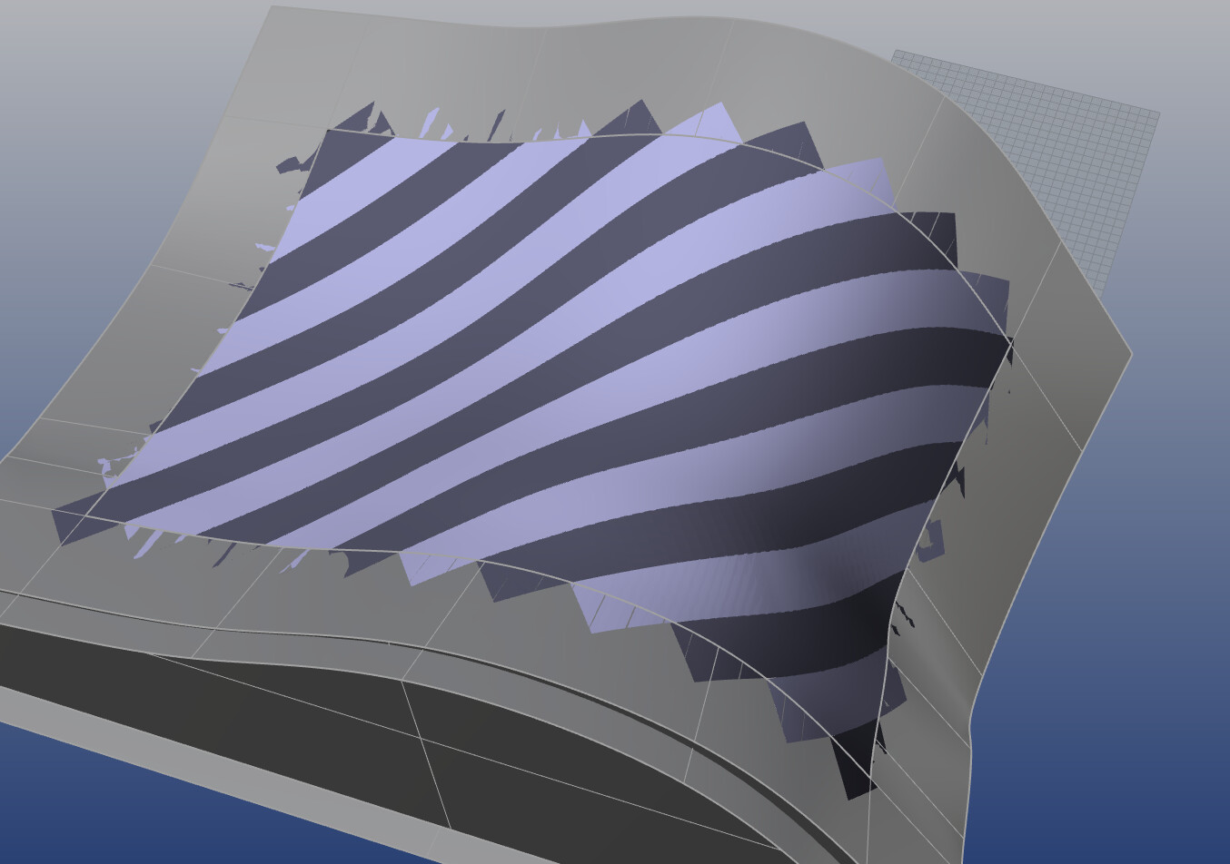
Again, this all looks like typical Z-fighting to me… and there’s really not much you can do about it, other than force specific triangles to land at slightly different depths…which I don’t think can be done in Common. You could probably try nudging things closer to the camera by changing the model transform ever so slightly in Z prior to drawing each tape, but I assure you that figuring out what “ever so slightly” should be can be a lesson in futility…since the depth buffer is not linear in OpenGL, and depths can/will vary drastically based on camera/target position and overall scene contents…basically anything that changes the near and far clipping planes will immediately cause different depth values to fall from frame to frame…so what once seemed like a good “nudge factor” may be way too much or way too little as the camera and scene change.

Rhino suffers from this (as do all 3D graphics engines) as well…Three coplanar objects will fight with each other:

But in this very specific case (specific types of planar objects), Rhino provides BringForward and MoveBack features that can be assigned per-object to get them display in the desired order…

But this only really works well because the objects are planar… However, curving, turning, bending surfaces that all fall on different depth values are always going to fight with other triangles that fall on those same depth values, and there’s currently no way to forcefully determine “who wins”

That being said… Your example above, where the wires are disappearing is probably because you’re drawing the wires first and then the meshes…and with depth writing OFF, the meshes are probably overwriting the wires where they intersect inside another mesh. If this is even possible (@dale can answer this), you could try flushing the pipeline after each specific draw and after each specific tape.

DrawMeshes();
FlushPipeline();
DrawWires();
FlushPipeline();

If that’s doable in Common, then it will force the meshes to get output before the wires, always (note: The order in which Rhino decides to output and flush things is based on cache size and cache overflow, so there’s no guarantee that just because you put a DrawA() before a DrawB(), that A goes out before B…which is why you need to flush things yourself if you want that type of guarantee…but again, I’m not sure if this can be done in Common.

And if you absolutely want all wires to show over all meshes, then I would draw all meshes first…then draw all wires.

for (int i = 0; i < count; i++)
{
DrawMesh(i);
FlushPipeline();
}

for (int i = 0; i < count; i++)
{
DrawWires(i);
FlushPipeline();
}

If FlushPipeline() has no equivalent in Common, I’m pretty sure @dale can easily provide you something.

-Jeff

There is DisplayPipeline.Flush().

https://developer.rhino3d.com/api/rhinocommon/rhino.display.displaypipeline/flush

– Dale