Hi,
I have an isir mechanism which is powered by gears and I would like to set a simulation in grasshopper before I lasercut my elements once again… ( I already did the real model 3 times and sth was always wrong and now I’m running out of time).
Could someone please help me run grasshopper kangaroo gear simulation?
Here is the file, everything is grouped and names so I believe you shouldn’t have a problem to find yourself. I’m gonna have a motor connected to the gear on the right in the model (called ‘bigger circle’) which should move the two smaller circles which will move the biggest gear which finally will move the blades making the iris mechanism close and open (depending which way it works).
I don’t see gear ratios defined anywhere in the model? Seems to me that if they were, you could easily calculate rotation angles for the dependent gears (the two smaller circles, the biggest gear and the blades) based on the slider angle for the ‘bigger circle’?
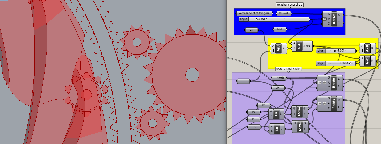
Later… like this. See ‘angle’ slider in blue ‘rotating bigger circle’ group and yellow groups that use teeth counts at each stage to calculate gear ratios. At each step, the rotation angles are reversed using an expression ("-x") on the ‘RotAx A’ inputs. It looks to me like the ‘rotating bigger circle’ angle must be limited to ~27.6 degrees, which closes the iris? This does not use Kangaroo.
Oh, by the way, the gears need some rotation alignment so the teeth won’t collide. And I disabled ‘Extrude’ at the end because it’s slow and prevents viewing the gears move as you move the slider.
I added ‘align’ sliders to each of the yellow groups to set rotation offsets that align the gears without affecting gear ratios. It’s easy to see many ways this complex mechanism can fail! The two ‘rotating small circles’ each require their own ‘align’ slider and all of the gears attached to the blades must also be aligned separately to fit the large ‘inner circle with teeths’, independent of the blades!(that’s critically important) I added one ‘align’ slider that affects them all but that won’t do the job.
Looking more closely, I see that in the first group at the top left (‘size of blade’s teeth’), you are scaling one tooth but using an off-center reference? The tooth appears to be distorted?
Finally, I have to wonder if it’s a good idea to have the driving gear (blue group ‘rotating bigger circle’) move only 30 degrees? Many teeth are never used. Would it be better instead to have the ‘rotating bigger circle’ connect directly to the ‘outer circle main gear’ (which rotates only 3.8 degrees), driven by a small gear on the motor? Or some other arrangment, maybe skipping the ‘rotating bigger circle’ and driving one of the two small gears directly?
To do that, you need to re-arrange components so that:
‘ArrPolar’ creates the fourteen blades and their gears, then
‘align’ rotation adjustments can be made on each gear separately without rotating its associated blade, then
apply rotation from ‘inner circle main gear’ to all fourteen pairs of blades and gears.
But I’m concerned about the rather crude gears and the minimal rotation, which could have a lot of “play” between them. The end-to-end gear ratio here is 0.46, meaning the blades rotate slightly more than twice the angle of the driving ‘rotating bigger circle’ gear. Are gears needed at all or would linkages work better, with more precision?
As for gears in Grasshopper, I found a few references that might be helpful: