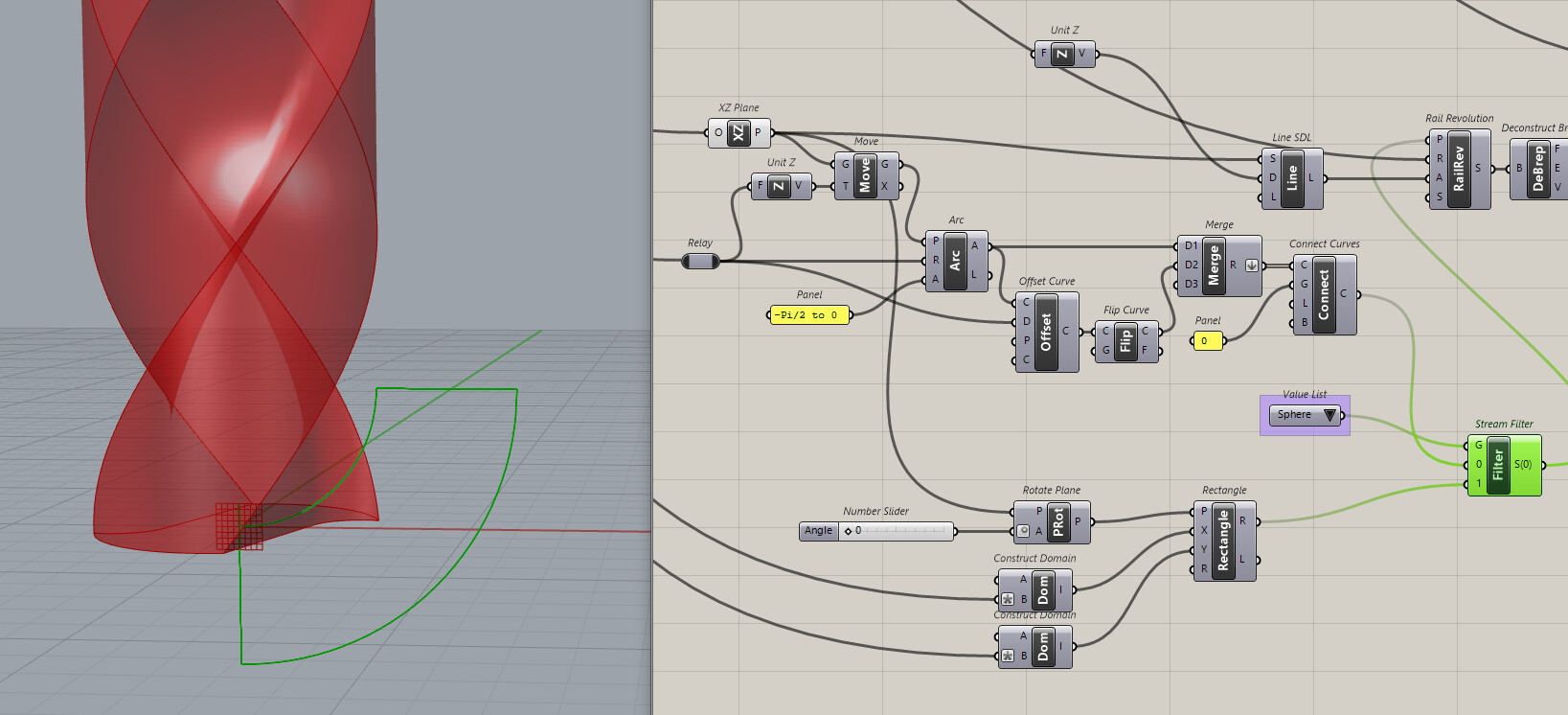
I think this design is pretty different from the previous one (and also much more complex) 
it might be possible to do in GH, probably I would use many (MANY) boolean subtractions from a base pipe with round caps? I think the best way to understand more might be to try to understand the way and order they have CNC-machined it?
the main issue is understanding its shape (if you want to reproduce that exactly as it is) and also introducing some parameters that are actually useful and “connect well” with each other, for which I have absolutely no idea 
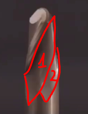
for instance, this surface looks like it’s a continuous one, and it could be the very first thing that was milled:
then this surface might be the second milling operation, with a slightly more steep angle:
the presence of this edge here:
makes me think that those long milling that moves down to the very end of the tool were done first:
I mean these ones, both of them, for each side
and as very last thing these surfaces here:

this dent that I see here:
makes me think that none of the initial thin surfaces that defines the silhouette of the tool, entirely lie on the very silhouette of a round-capped pipe… but at the same time, it might easily be that those silhouettes just recede a little bit just at their very ends, in such a way to allow for the chips to have space to be thrown away?
long story short, if I had to guess the order of the operations, I would say:
- turning the external silhouette profile (which is also the residue of surface #1) with a revolve
- thinning the core with two milling (Solid difference using two lofts along a conical spiral)
- straight cuts (solid difference)

- this edge here (I guess solid difference once again?)
how to put that together is not very straightforward… I would start with revolving the profile, the using maybe something like this ( Creating a spiral form - #14 by Birk_Binnard ) to create the conical spirals on which to build the solids for the boolean subtraction at step 2, and see where it goes