Hi everyone, as some of you might have seen, with the help of some of you, I’ve been working on a script to add panels to a surface so I can control the dimensions more accurately, rather than using lunchbox.
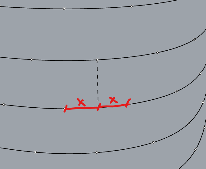
I started by contouring a surface, think of these contour lines as the floor slabs of a building. I started by dividing the even levels by a certain number, and the odd ones by twice that number, and culled out half of those points on odd levels, so I could do a zig zag pattern going vertically. The problem is that since this is not a symmetrical shape the points above does not fall between the center of the points below, vice versa. It is slightly off based on the location on the surface. It’s hard to explain, but see the image below, those two X dimensions should be equal basically.
How can I go by something like this? Maybe dropping each point down a level, and use something like curveclosestpoint to find the middle and go from there? Since the panels will be flat, I don’t care about the curvature, as long as the direct distance from the points on the sides to the mid point are equal, that would work!
Divide Curve.gh (17.4 KB)
I don’t understand the problem you describe? All your curves are 395.585468 units long, which is not evenly divisible by 6 (or 3). Is that the problem? The highlighted green points are start/end points.
I see two problems with this construction :
- you use Divide Length, but the length is not divisible by 6 so your last segment will not have a length of 6. Even with that, the length is calculated along the curve, it’s not the distance between the points. This would require to use
Divide Distance.
- All your curves seem identical but slightly rotated/translated. So, the overall surface is not vertical. I don’t see how it’s mathematically possible to align each point of curve {N+1} along the middle betwen points of curve {N}, and simultaneously guarantee a constant distance between all those points.
2 Likes
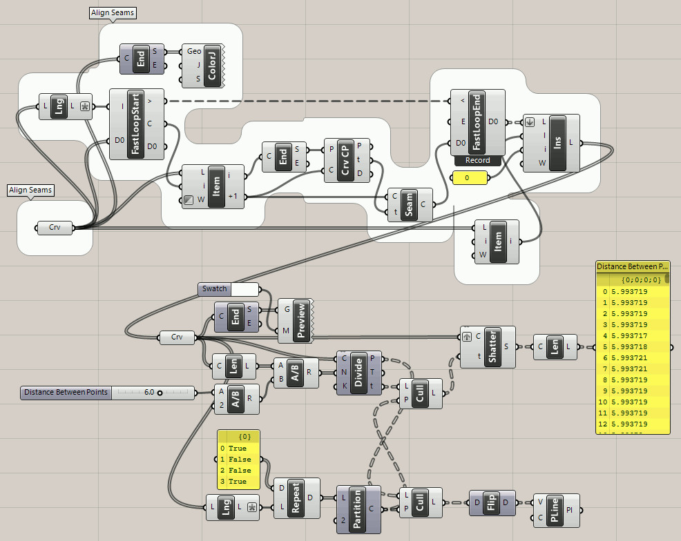
Correct! I made that mistake myself and quickly deleted my post. This code uses a different method to allocate the points, using the ‘Distance Between Points’ slider only as a guide. The length of each curve (all are the same) is divided by the slider value to calculate the number of divisions used by Divide Curve, not Divide Length. The text panel shows the length of the curved between points, which are all the same to four decimal places.
Divide Curve_2023Feb14b.gh (24.4 KB)
(Oh dear, I left the slider value at 6.6 instead of 6.0…  Code is otherwise fine.)
Actually, curve lengths are divided by half the slider value to double the number of points and the cull pattern is reversed on each row, an old method from brick laying days (in GH):
1 Like
Here is a C# script that divides the first curve into equally spaced points (along the curve), then builds a polyline from there. Then, for each segment, takes the perpendicular frame at the middle and gets the closest intersection with the above curve. Rinse and repeat to the top.
All “midpoints” are equidistant to the two surrounding points of the curve below. But, none of the panels have the same width (varying from 5.78 to 5.92).
Divide Curve.gh (29.9 KB)
Nice. Sounds similar to a method I used to center points on a gradient dot pattern using Anemone.
The perimeter is a “Race Track Oval” shape curve so the dots are closer together in the curved parts and farther apart where it’s straight.
The length of the curve or how many points I divide by can be changed, that is not the problem.
To better explain the issue, I will give you an example. If I project the points on level 2 down to level 1. I would like those points I just projected to be the middle point between the existing points on level 1. On a perfect cylinder, that is how it works, but when the shape is not symmetrical, it is off a bit.(see the diagram on the first post, I am trying to get those X dimensions to be equal if possible)
Correct, maybe it is not mathematically possible, but I wanted check with you all before I give up on it. And that is right, the curves are identical but rotate as they go up. This is a small portion of a test I am working on, the actual shape is a tower. These rotations help me get a curvy look on the surface.
I will inspect the scripts you all provided, thank you!
That doesn’t sound realistic when the curves rotate as they go up, which wasn’t obvious to me.
1 Like
Yes, not a problem then. One last question for you - as I mentioned I divided the odd curves by 6, and the even curves by 3. The idea was that I would cull every other point on the odd ones so I could get that shifted look at every level.
I just tried dividedistance, which is exactly what I need and gives me same exact width all around, but since I am dividing the odd ones by 3, the actual distance I need after culling, ends up being like 5’ - 11 3/4", not 6. Is it possible to offset the start of the division by a certain distance to shift the entire point group(the same way you would enter the “start” on a series component), rather than the cull trick I am currently using?
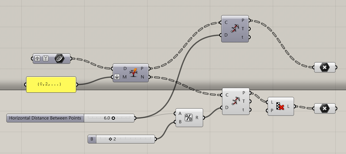
You can change the seam of the curve 3 units after the current start point.
I still fail to see how this would guarantee that the midpoints are aligned, and also keep in mind that the last segment will not have a length of 6.
ChangeSeamDivideDistance.gh (10.6 KB)
1 Like
If the mid points don’t align, that would be fine, but I think having a constant width all around is currently more important. As you said, I don’t think I can have both the mids points working, and running with the same width all around due to the shape we have. So, gotta pick one of them it seems like. Thank you!
I haven’t read the latest posts yet… but added the white group (below) to align the seams of all the curves before doing the same as my version ‘b’ yesterday.
Divide Curve_2023Feb15a.gh (34.8 KB)
(DEPRECATED due to error, see version ‘15b’ below)
P.S. No need to repeat what you said, I read it the first time and studied your code. The difference between distance and equal length curve segments is significant! And now aligning the mid-points is not important? The goal posts are moving a little too fast, let’s slow down and make sure you fully understand the replies you have received, eh.
1 Like
Yes, I read the answers from both of you and inspected the scripts you provided, hence me changing the goal post. You said that, referring to mid points aligning,
“That doesn’t sound realistic when the curves rotate as they go up, which wasn’t obvious to me.”
So, I figured that if it is not possible to align the mid points without having to change the distance between the points, then I’d rather have the same distance between points all around, rather then trying to figure something out that may not be possible, as you said. Thanks for your solutions, and enjoy the rest of your day.
That was before I thought of aligning the curve seams with Anemone, as I did in today’s post. And it still doesn’t sound realistic to “project” the points down when the curves are rotated, but aligning the seams should give a similar effect. @magicteddy’s C# code also addresses that issue, I think?
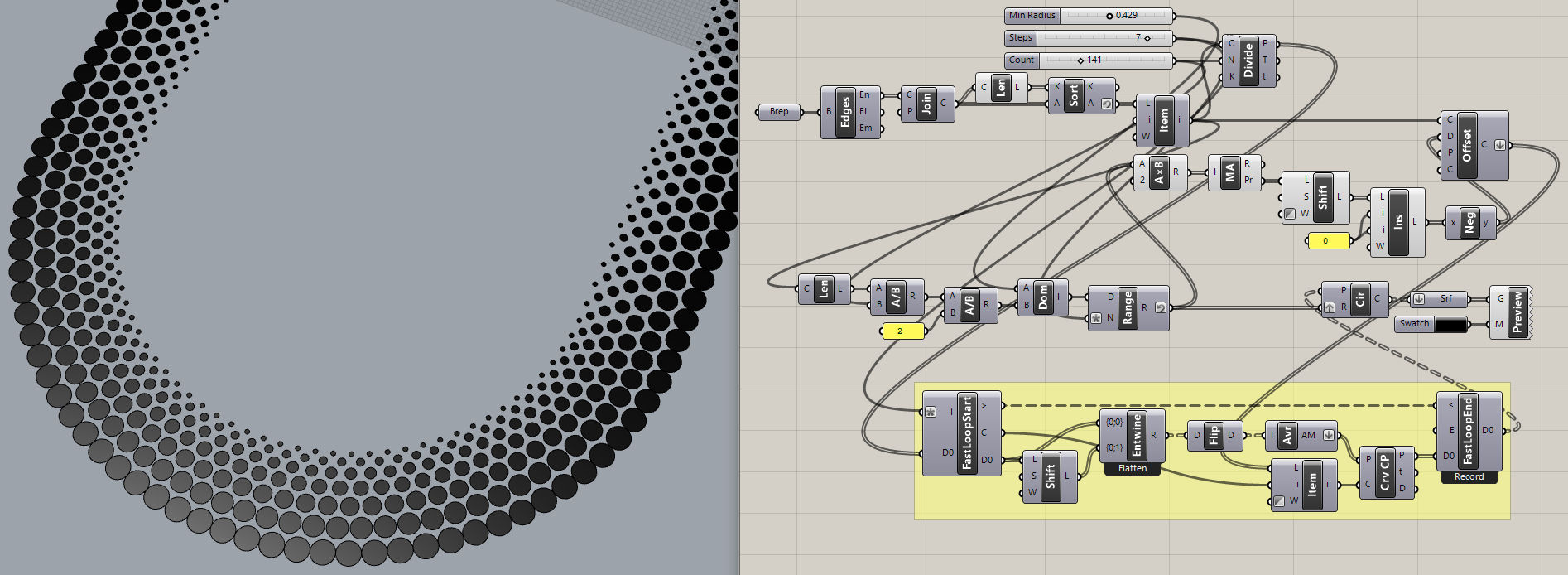
FYI, the ‘Gradient Dot Pattern’ I referred to was later adapted to this curved surface, so what at first seems impossible sometimes turns out to just need a different point of view:

I rushed coding that Anemone loop and made a mistake. The colored points show the original start points before the loop, the white points show the start/end of the aligned seams, after the loop.
Divide Curve_2023Feb15b.gh (41.2 KB)
Have a nice day.
1 Like