I am currently working with a BREP that includes bent surfaces, some bending upward and others bending downward. In the example shown below, there are two surfaces bending upward and one bending downward.
I want to consistently determine the bending angles relative to a reference face, such that:
Bends downward are represented by a negative angle.
Bends upward are represented by a positive angle.
The challenge is to establish a reliable method to calculate these angles with consistent results, regardless of the orientation or complexity of the geometry. The solution should account for the direction of bending relative to the reference face and produce the correct sign for the angle.
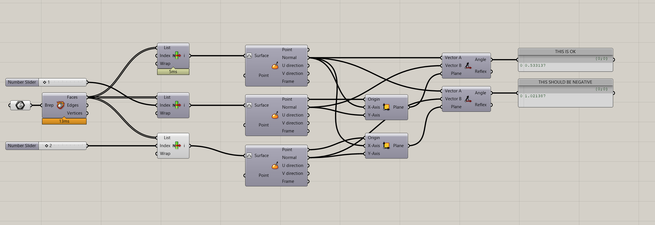
I’m not sure, but - after playing around with vectors - it looks like the angle between two vectors will always be given as a positive.
With that in mind, the only thing I could think of was to compare the origin points of the two surfaces being compared. If the Z of the origin of the first plane is larger than the Z of the origin of second plane, then make the angle negative.
(Edit)
Conceptually, it might be easier to think of it the other way…if the Z of the origin of the second plane is smaller, then make the angle negative. So in this second one I used the lesser-than components.
@webdunce Amazing! I tried your second approach and made it Z-axis independent. For now, it worked for all my cases I tried. Thanks!
For anyone stumbling over this again…
        /// <summary>
        /// Calculates the relative angle between two Brep faces.
        /// </summary>
        /// <param name="currentFace">The current Brep face.</param>
        /// <param name="otherFace">The other Brep face to compare against.</param>
        /// <returns>The relative angle in radians. If the other face is behind the current face, the angle is negative.</returns>
        public static double CalculateRelativeAngleBetweenFaces(
    public static double CalculateRelativeAngleBetweenFaces(
        BrepFace currentFace,
        BrepFace otherFace)
    {
            var normalCurrent = currentFace.NormalAt(0.5, 0.5);
            var normalOther = otherFace.NormalAt(0.5, 0.5);

            var currentPlane = new Plane(currentFace.PointAt(0.5, 0.5), normalCurrent);

            var uDomain = otherFace.Domain(0);
            var vDomain = otherFace.Domain(1);
            var otherFaceMidPoint = otherFace.PointAt(uDomain.Mid, vDomain.Mid);

            var relation = PointPlaneRelation(currentPlane, otherFaceMidPoint);

            normalCurrent.Unitize();
            normalOther.Unitize();

            var angleRad = Vector3d.VectorAngle(normalCurrent, normalOther);
            var angleDeg = RhinoMath.ToDegrees(angleRad);

            if (relation < 0)
                angleDeg = -angleDeg;

            return angleDeg;
    }


        /// <summary>
        /// Determines the relation of a point to a plane.
        /// </summary>
        /// <param name="plane">The plane to compare against.</param>
        /// <param name="point">The point to compare.</param>
        /// <param name="tolerance">The tolerance for determining the relation.</param>
        /// <returns>
        /// Returns 0 if the point is on the plane within the given tolerance.
        /// Returns 1 if the point is above the plane.
        /// Returns -1 if the point is below the plane.
        /// </returns>
        public static int PointPlaneRelation(Plane plane, Point3d point, double tolerance = 1e-12)
        {
            var vec = point - plane.Origin;
            var d = vec * plane.Normal;

            if (Math.Abs(d) < tolerance)
                return 0;

            return (d > 0) ? 1 : -1;
        }
let’s say that -without changing any angle between faces in the brep- I just rotate the whole Brep a little bit… reading the Z coordinate doesn’t look like a reliable solution:
@inno I agree, but I think the approach if you make it independent of the z-axis works. At least it worked on the breps I tried it on so far.
In the video, I implemented the code shared before, and I can rotate it as I want; the result stays the same.eo i implemented the code shared before and i can rotate it as i want the result stays the same.
as far as I can understand from your code (I’m more of a Python reader to be honest so I could easily be wrong)
that approach is based on the direction of the surface Normals? I’m more about the reliability of that
if you pass your brep through something like this (will flip all the surface normals alltogether)
@inno yes exactly, so the normals of the brep should point all outward or all inward; otherwise, it will not work properly. There could be maybe another algorithm That makes sure of that for better reliability, but for my current problem, I didn’t run into it…yet
I put my snippet in a GH c# component for better accessibility.
In theory yes (there’s a RC Method that reports that). But the general case of this is what happens if the Brep is a valid open and manifold result of joined BrepFaces. With this (and some other things) in mind … well … yes there’s a far better algo to manage that sort of stuff (using Dot/Cross products + VectorAngles taking into account a properly oriented RefPlane blah blah). I’ll post an indicative C# when I’ll be in the practice.
I made a pure grasshopper version that seems to allow the original brep to be rotated and still seems to give the correct angle. I did it just for the pure challenge of it.
not trying to mess things up, but I think that is not enough
it is exactly the thing I was pointing out in my previous post
in this example, the bottom part is supplied the very same geometry, the only thing that changes is the flipped direction of ALL the Normals altogether, and the same measured angle went from negative to positive:
Only solution I can come up with for this problem is to give the user a way to visualize the normals of the two planes being compared and then give the user the option to flip them. In this case, I do not affect the normals of the original brep, though.
But it will be probably always necessary that a user is able to flip outside inside / (±), or the BREP’s need to come in a very standardized way?
In my case, I’m building a sheet metal plugin, and the user needs to select a base face anyway for defining inside/outside of the sheet.
So as long as the ± is applied consistently being it -(up) +(down) or +(up) -(down) that would already give a pretty good understanding of the topology, or would you disagree with that?
So in this case, I defined the specifications wrong.
So probably with the cross product and edge orientation and so on you probably still need to set a base direction anyway. But i like the problem and curios for other solutions
let’s say that when I see the Brep on the screen, my mind already figures out what is up and what is down in reference to the World coordinate system: I think one safe-fail method might be to just take “the most meaningful” normal orientation on your input Brep, and perform a check first and eventually flip normals
here it considers as “most meaningful” the most connected face (Face|Face-wise) and check if its Normal angle with world_Z axis is bigger or smaller than 90 degrees: if it’s smaller it means the face already has normal oriented up-ish and keep things as they are
if it’s bigger it just flips the whole brep and uses that flipped version for any further calculation
at the same time, by phisically rotating the Brep in such a way the most meaningful face normal becomes opposite-ish to world_Z, the positive angles will become negative -and the other way around- because what the user expects to be a positive angle value is still linked to world coordinate system:
for sure, the rule of how to pick the most meaningful face might be refined it could be the face with highest area, or even selected by the user… the underlying main point is to keep the “inside” and “outside” of the metal sheet consistent along all its faces, regardless of how many they are, and how they are oriented (for this reason I believe “inheriting” the flipped/non-flipped Normals from a reference Face is a viable way to solve the issue)
No (provited that the Normals are “rational” - more on that later). In fact today is a good day > why bother with the practice? Let’s ride some Ducati. But battery is dead. So until the CTEK does(?) something I’ve started writing some lines. But battery is OK (is it?) before finishing the demo C# (adding more dots here and there). Get a preview (paths: first dim: parent/master Face idx, sec dim: adjacent Face idx, dots shown are the involved Faces indices):
Looks very promising! As well does the Ducati, probably.
Do you get the adjacent Face + shared edge? Then the use the edge direction of the base face? + base face normal + other face normal to determine the sign (Dot Product)?
Well … ride started with full sunshine. After a while rain. 998S stopped (as expected). Only problem is that I was in the middle of nowhere (and I hate mobile phones so I don’t have any). Porca Miseria (should I get the R1200S: pig ugly - nor is a sports bike - but it works).
Get the “reference” planar Face (the master so to speak) and the adjacent Faces/Edges and the Normal.
For each adjacent planar Face get the adjacent Edges and the Normal. Get the common Edges using the ref Face Edges (a classic Array - of Type int - intersection).
If the intersection yields one Edge - by index (must be a Line - obviously) then this is the common Edge.
If the intersection yields more Edges (must be Lines) then all must be colinear (see pic below) (otherwise a bending has no meaning). If OK get one as the common Edge. If not skip that Face.
Get the Normals Angle as shown above (spot the way that the anglePlane is defined - can you think the reason ???). Get the sign : pos if angle<Math.PI, neg if not, N/A if angle is 0 or Math.PI.
After getting the sign … if the angle is > Math.PI then angle = Math.PI*2 - angle.
Store all that mess to Trees/Lists/Arrays (of Type object) etc etc.
Do some visual aids (shown above): say Green for pos, Red for neg. Use TextDots as well (if you want include the common Edge Idx as well).
Provided that there’s no rain around go ride the proper thing.
i search for all panels in this model (one edge could have only 2
faces)
connectivity is needed (EE, EP, PP)
i will take the first panel (or face) and i compare the pan normal
with global Z
if pan normal is aprox. equal to Z (with some tolerance) i know
that the panel is orientated upward. If not, it is downward.
according to the orientation of the first panel and based on EE
connectivity information i will orientate all other panels according
to the neighbors. In other words i will flipp or not.
At the end i have all panels orientated inn or out. If its wrong, you can flipp all panels and you have the oposite direction.
In case of (rationally defined) fillets … just modify the adjacent Faces/Edges query: i.e. given a Planar Face (the reference one) then if some Adjacent Face is some sort of “cylinder segment: i.e. a fillet” then find/work with the “next” adjacent Face etc etc.
Tip: use as many public stuff as possible in order to avoid calling Methods via a myriad of vars.