Hello experts! A warm hello from Austria. I have a question for you. How would you model a reception desk from planar triangles. I would like to start with a cuboid. I have to do the design and there can’t be warped surfaces. Thank you for your help! A beginner
after the first days of the course - Rhino is my favorite animal !!!
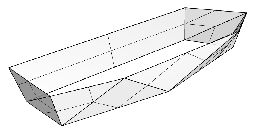
I’d start drawing the bottom and top defining polylines in the top view, and move the top one to the required height in perspective or one of the side views.
Next you could start replacing non-planar surfaces by substituting non-planar ones with triangular faces with SrfPt. As @Tom_P has already pointed out, tris are always planar.
You can use the existing surfaces as guides and references, but make sure to delete them after your done.
in top view: parallel segments will result in planar surfaces.
(2) using _srfPt
(A) clicking 3 Points will result in a trimmed surface.
(B) clicking 3 Points - and the last point a seccond time will result in a untrimmed surface with two coincident points.
screenshots shows (bottom) initial triangular surface with control points on - and untrimmed (top row) surfaces.
I’d suggest modelling this sort of triangulated object with a meshes. The advantage of a mesh with triangular faces is that you can drag the points and the neighboring faces follow. Not the case when modelling with nurbs. In the end you can still convert everything to nurbs / surfaces but for formfinding, I’d say it’s easier with a mesh.
If this is a design piece for production, I’d surely go for polysurface/solid modelling.
Also the mesh modelling tools in Rhino are far inferior to the n.u.r.b.s. ones, and a nightmare if you want to introduce Boolean operations, fillets, chamfers, or similar manipulations.
Good points on both side, which will inevitably come down to the project and desired workflow. A large triangulated façade in the conceptual phase is going to be benefited by working in a mesh, the fabrication and detail would go towards solids & surfaces.
Adding agreement here: start with triangulated mesh like Martin suggests, then do all your detailing to a Nurbs model that you can obtain from the triangulated mesh using MeshToNurbs.
You can even play with grasshopper a bit here. Maybe try the tri-mesh component, that will mesh into triangle any sort of blob/mesh/brep.
You could also hook your desired form mesh into a grasshopper input for MeshToNurbs and then add all the detailing booleans parametrically. And when you see that you need to change the base form, you do that at the original tri-mesh level.